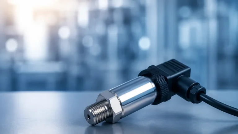
Wet Wet Differential Pressure Transmitter
Wet Wet Differential Pressure Transmitter
In the landscape of industrial process control, the wet wet differential pressure transmitter stands as a fundamental instrument for monitoring fluid dynamics, tank levels, and filtration efficiency. Unlike "wet-dry" configurations where only one side of the sensor is exposed to a liquid medium, a wet-wet system involves both the high-pressure and low-pressure ports being in direct contact with liquid process media. This requirement is common in pressurized tank level applications, liquid flow measurement across orifice plates, and hydraulic system monitoring.
Selecting and implementing these instruments requires a deep understanding of hydrostatic principles, material compatibility, and the mechanical nuances of impulse line installation. As a professional manufacturer, Welk provides a range of Main Page solutions designed to meet the rigorous demands of water treatment, chemical processing, and oil and gas industries.
Measurement Principles of Wet-Wet DP Transmitters
The core function of a wet wet differential pressure transmitter is to measure the difference between two pressure points in a liquid system. The device typically utilizes a sensing element—often a piezoresistive silicon chip or a capacitive cell—isolated from the process by two flexible diaphragms.
The Hydrostatic Equation
In level measurement applications for pressurized vessels, the transmitter calculates the liquid height by subtracting the gas-phase pressure (top of the tank) from the total pressure at the bottom. The formula used is:
ΔP = (ρ × g × h) + (P_surface – P_surface)
Since the "wet" low-pressure side is connected to the top of the tank, the surface pressure ($P_{surface}$) cancels out, leaving only the pressure exerted by the liquid column ($
ho imes g imes h$). This allows for accurate level readings regardless of fluctuations in the tank's internal blanket pressure.
Flow Measurement (Bernoulli’s Principle)
When used for flow, the transmitter measures the pressure drop across a primary flow element, such as an orifice plate or Venturi tube. According to Bernoulli's principle, the square root of the differential pressure is proportional to the flow rate. In a wet-wet setup, both impulse lines are filled with the process liquid, ensuring that the pressure transmitted to the sensor diaphragms is a true representation of the fluid's kinetic and potential energy changes.
Key Evaluation Criteria for Industrial Selection
Choosing the right transmitter involves more than just matching a pressure range. Engineers must evaluate the specific environmental and chemical conditions of the application. The following table outlines the primary technical specifications to consider during the procurement phase:
| Feature | Specification Detail | Importance |
| :— | :— | :— |
| Static Pressure Rating | Up to 160 bar, 250 bar, or 400 bar | The maximum pressure the housing can withstand without failing. |
| Wetted Materials | SS316L, Hastelloy C, Tantalum, Monel | Critical for chemical compatibility and preventing corrosion. |
| Turndown Ratio | 10:1 to 100:1 | Defines the rangeability of the instrument while maintaining accuracy. |
| Accuracy Class | 0.075%, 0.1%, or 0.2% FS | Determines the precision of the output signal (4-20mA/HART). |
| Fill Fluid | Silicone Oil, Fluorinated Oil, Food-grade Oil | Must be chosen based on process temperature and oxygen service needs. |
Static Pressure vs. Differential Pressure
A common point of confusion is the difference between static pressure and differential pressure. A wet wet differential pressure transmitter might be rated for a static pressure of 100 bar, but it may only be measuring a differential range of 0 to 500 mbar (50 kPa). It is vital to ensure that the sensor capsule can handle the full line pressure on both sides simultaneously without shifting the zero point significantly.
Practical Installation Considerations
The reliability of a wet-wet measurement system is often determined by the quality of the installation. Because both sides are liquid-filled, air entrapment is the primary enemy of accuracy.
1. Impulse Line Routing: For liquid applications, the transmitter should ideally be mounted below the process tapping points. This allows any air bubbles to naturally rise back into the process pipe or tank. The impulse lines should have a minimum slope of 1:12 (approx. 8%) to facilitate this degassing.
2. Manifold Integration: A three-valve or five-valve manifold is essential. These allow the operator to isolate the transmitter from the process, equalize the pressure for zero-point calibration, and bleed the system of air or contaminants without shutting down the entire line.
3. Temperature Gradients: If one impulse line is exposed to heat (e.g., sunlight or a nearby steam pipe) while the other remains cool, the density of the liquid in the lines will differ. This creates a "false" differential pressure. Insulation or heat tracing may be required to maintain thermal equilibrium between the two "wet" legs.
Common Risks and Limitations
While highly versatile, wet-wet DP transmitters are subject to specific operational risks that can lead to measurement drift or hardware failure.
* Air Pockets: In a wet-wet system, a single trapped air bubble in the low-pressure impulse line can cause a significant offset in level or flow readings. Regular "bleeding" of the lines is a standard maintenance requirement.
* Overpressure Events: If a technician opens the high-pressure valve while the low-pressure side is vented to the atmosphere (and the bypass valve is closed), the sensor may experience a full line-pressure differential. High-quality transmitters include overpressure protection diaphragms to prevent permanent deformation of the sensing element.
* Sedimentation: In wastewater or slurry applications, solids can settle in the impulse lines, effectively "plugging" the transmitter. In these cases, remote seals (diaphragm seals) are often used to keep the process media out of the small-bore tubing entirely.
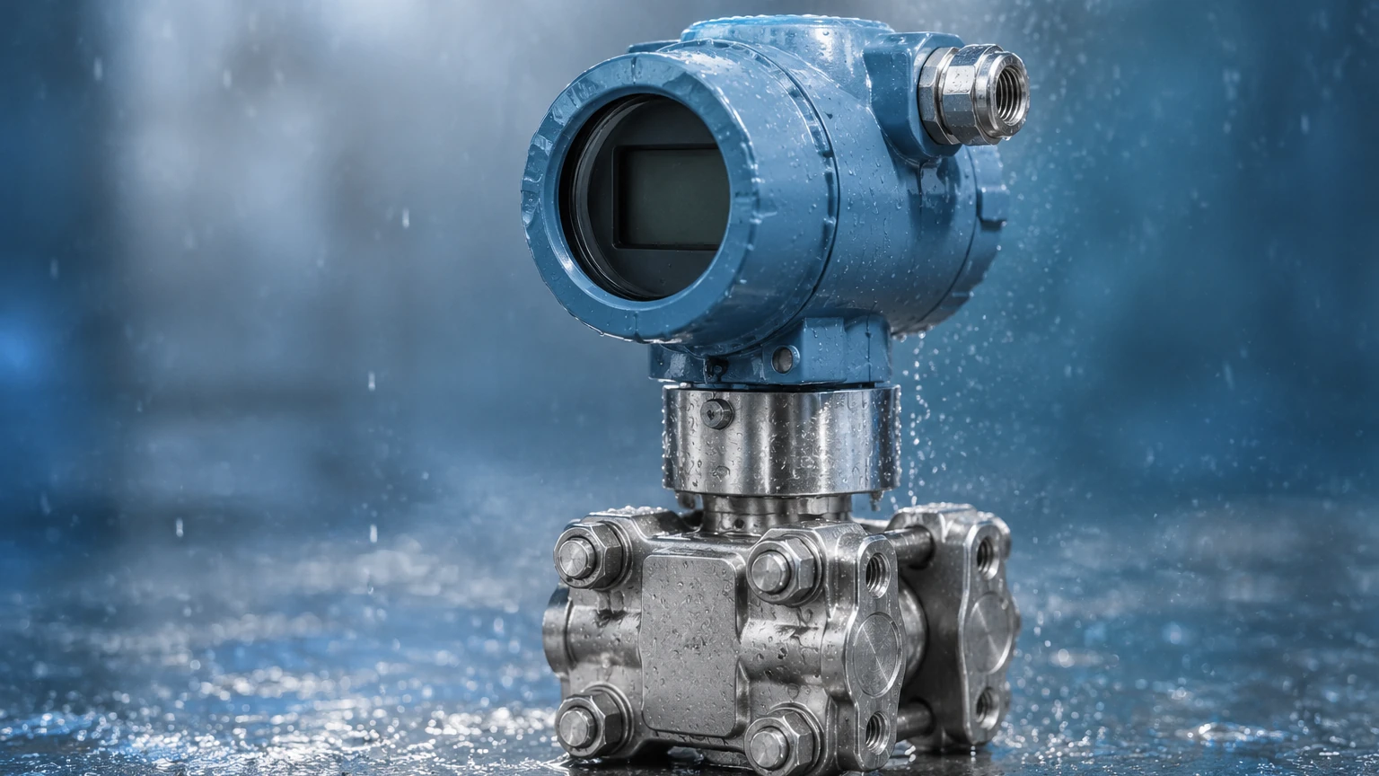
Comparison: Wet-Wet vs. Remote Diaphragm Seals
Engineers often debate whether to use traditional impulse lines (wet-wet) or remote diaphragm seals. The choice usually depends on the process temperature and the nature of the fluid.
* Standard Wet-Wet (Impulse Lines): More cost-effective and easier to repair in the field. However, they are prone to freezing in cold climates and require more frequent maintenance to manage air pockets and leaks.
* Remote Diaphragm Seals: These use capillaries filled with a transmission fluid to connect the process to the transmitter. They eliminate the need for impulse lines and are ideal for hygienic applications or highly corrosive media. The trade-off is increased cost and potential temperature-induced errors due to the expansion of the fill fluid in the capillaries.
Frequently Asked Questions (FAQ)
Q: Can a wet-wet DP transmitter be used for gas applications?
A: While technically possible, it is not recommended. For gas, a "dry-dry" or "wet-dry" setup is used to prevent liquid condensate from collecting in the lines, which would create an erroneous head pressure.
Q: How often should I calibrate my wet-wet transmitter?
A: For most industrial applications, an annual calibration check is sufficient. However, the "zero" should be checked more frequently, especially after significant temperature swings or system maintenance.
Q: What is the benefit of a 5-valve manifold over a 3-valve manifold?
A: A 5-valve manifold includes two additional vent/drain valves. This allows the operator to safely bleed the impulse lines into a container or waste system without disconnecting any fittings, making it the preferred choice for hazardous or "wet" liquid systems.
Conclusion and Next Steps
Implementing a wet wet differential pressure transmitter requires a balance of theoretical knowledge and practical engineering. By ensuring that wetted materials are compatible with the process and that installation avoids air entrapment, operators can achieve high-precision measurements for years.
Before finalizing a project specification, technical teams should confirm:
1. The maximum static line pressure of the system.
2. The specific gravity of the liquid at operating temperature.
3. The necessity of chemical-resistant coatings or specialized diaphragm materials.
For those seeking reliable, cost-effective level and pressure measurement hardware, exploring the Main Page of a dedicated manufacturer like Welk provides access to the necessary technical documentation and OEM/ODM customization options required for complex industrial automation environments.