What Is a Flowline
What Is a Flowline
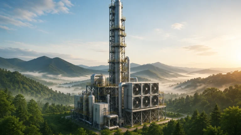
In the complex landscape of industrial fluid management and upstream oil and gas production, the term "flowline" refers to a critical component of the transport infrastructure. Understanding what is a flowline requires looking beyond a simple pipe; it is the primary arterial link that connects a single wellhead to a manifold, a process facility, or a storage unit.
For engineers and facility managers, the flowline represents the first stage of fluid handling where raw, unprocessed materials—often a multiphase mixture of oil, gas, water, and sediment—are moved under pressure. Because these fluids are often volatile and abrasive, the design, material selection, and monitoring of flowlines are essential for operational safety and efficiency. This guide explores the technical principles of flowlines, their relationship with level measurement technologies, and the practical considerations for their implementation.
The Fundamental Principles of Flowline Operation
To define what is a flowline in a technical sense, one must distinguish it from other types of industrial piping. While gathering lines collect fluids from multiple sources, a flowline typically serves an individual well or a small cluster. Its primary function is to transport the "live" well stream to the first stage of separation.
Multiphase Flow Dynamics
Flowlines rarely carry a single substance. Instead, they operate under multiphase flow conditions. The ratio of liquid to gas, the velocity of the fluid, and the pressure within the line dictate the flow regime—whether it is bubble flow, slug flow, or annular flow. Managing these regimes is vital because irregular flow (such as slugging) can cause mechanical stress on the pipe and create turbulence in downstream vessels, such as separators.
Pressure and Temperature Management
Fluids exiting a wellhead are often at high temperatures (sometimes exceeding 100°C / 212°F) and high pressures. As the fluid moves through the flowline, it loses energy due to friction and heat transfer to the environment. If the temperature drops too low, waxes or hydrates can form, potentially plugging the line. Consequently, flowlines are often insulated or equipped with heat tracing to maintain fluid mobility.
Technical Components and Material Selection
Defining what is a flowline also involves understanding its physical construction. The choice of material is dictated by the chemical composition of the fluid, specifically the presence of corrosive elements like hydrogen sulfide (H2S) or carbon dioxide (CO2).
1. Carbon Steel: The most common material for non-corrosive environments due to its cost-effectiveness and strength.
2. Corrosion Resistant Alloys (CRA): Used for "sour" service where H2S is present. This includes stainless steel or duplex steel.
3. Flexible Pipe: Often used in offshore applications, flexible flowlines consist of multiple layers of polymer and steel to withstand high external pressures and movement.
4. Reinforced Thermoplastic Pipes (RTP): Increasingly used in onshore applications to prevent corrosion and simplify installation.
The Critical Link: Flowlines and Level Measurement
While a flowline transports the fluid, the destination of that fluid is typically a separator or a surge tank. This is where the transition from transport to processing occurs, and where accurate level measurement becomes the most critical factor for plant safety.
When fluids arrive from a flowline, they enter a vessel where the gas must be separated from the liquids. To manage this process, engineers must monitor the interface levels (oil/water) and the overall liquid level. Welk provides specialized instrumentation to handle the turbulent conditions often found at the end of a flowline. For those seeking specific hardware solutions, you can Review product options and application support to see how different technologies integrate with these systems.
Measurement Principles for Flowline-Connected Vessels
Before recommending a specific sensor, it is important to understand the physics of measurement in these environments:
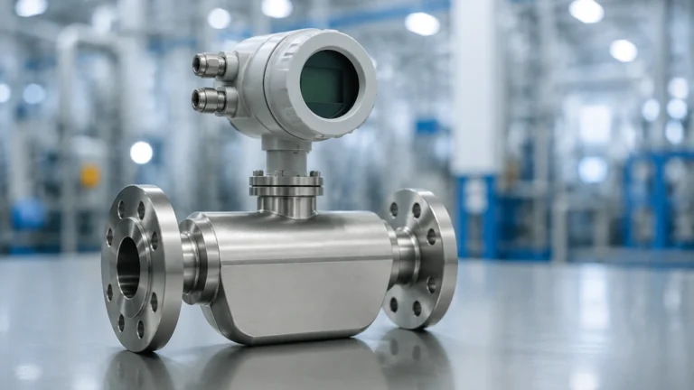
* Radar (Time Domain Reflectometry or FMCW): Radar level meters emit electromagnetic pulses that reflect off the liquid surface. Because radar is unaffected by pressure changes or the heavy vapors often present in flowline discharge, it is the gold standard for high-pressure separators.
* Ultrasonic: These sensors use sound waves. While cost-effective, they are generally limited to atmospheric or low-pressure tanks because the speed of sound changes with gas density and temperature, which can fluctuate wildly at a flowline's terminus.
* Hydrostatic: This method measures the pressure exerted by the liquid column. It is highly reliable for constant-density liquids but requires compensation if the oil/water ratio from the flowline changes frequently.
Selection Criteria for Level Measurement in Flowline Systems
Choosing the right instrumentation depends on the specific characteristics of the flowline output. The following table provides a comparison for selecting level sensors for vessels receiving flowline fluids.
| Feature | Radar Level Meters | Ultrasonic Sensors | Hydrostatic Transmitters |
| :— | :— | :— | :— |
| Pressure Range | Up to 400 bar (5800 psi) | Atmospheric only | Limited by flange rating |
| Temperature | Up to 450°C (842°F) | Max 80°C (176°F) | Up to 120°C (248°F) |
| Accuracy | ±1 mm to ±5 mm | ±0.25% of range | ±0.1% to ±0.5% |
| Vapor Sensitivity | Immune | Highly Sensitive | Immune |
| Maintenance | Low (No moving parts) | Low | Medium (Diaphragm cleaning) |
Installation and Maintenance Considerations
When installing instrumentation at the junction of a flowline and a process vessel, several engineering factors must be addressed to ensure long-term reliability.
Turbulence and Stilling Wells
The high velocity of fluids exiting a flowline can create significant surface turbulence in the receiving tank. For non-contact sensors like radar, a stilling well (a perforated pipe inside the tank) is often recommended. This pipe acts as a baffle, providing a calm surface for the measurement signal while allowing the liquid level to equalize with the rest of the tank.
Pigging Operations
Flowlines require regular cleaning and inspection, a process known as "pigging." A device called a "pig" is launched through the flowline to scrape away wax, scale, or debris. Instrumentation must be installed in a way that does not interfere with pig launchers or receivers, and sensors must be robust enough to withstand the pressure surges associated with pigging cycles.
Corrosion and Erosion Monitoring
Because flowlines carry raw fluids, they are susceptible to internal erosion from sand and corrosion from acid gases. Ultrasonic thickness gauges are often used on the exterior of the flowline to monitor wall thinning without interrupting production.
Common Challenges and Risks
Understanding what is a flowline also requires awareness of the operational risks involved:
* Slugging: This occurs when liquid and gas travel at different speeds, causing large "plugs" of liquid to hit the separator. This can overwhelm level control systems and lead to high-level alarms or emergency shutdowns.
* Emulsions: The turbulence within a flowline can mix oil and water so thoroughly that they form a stable emulsion. This makes interface level measurement extremely difficult for standard hydrostatic or capacitance probes.
* Sand Production: In older wells, sand may be carried through the flowline. This sand can settle in the bottom of separators, burying hydrostatic sensors or interfering with ultrasonic signals.
Frequently Asked Questions (FAQ)
Q: What is the difference between a flowline and a pipeline?
A: A flowline is a specific type of pipeline used in the initial stage of production (wellhead to process). The term "pipeline" is more general and usually refers to long-distance transport of processed fluids between facilities or regions.
Q: Can I use ultrasonic sensors on a flowline-connected separator?
A: It is generally not recommended if the separator operates under pressure or contains heavy hydrocarbon vapors, as these conditions significantly degrade ultrasonic signal accuracy. Radar is the preferred non-contact alternative.
Q: How long can a flowline be?
A: Flowlines can range from a few dozen meters to several kilometers, depending on the distance between the wellhead and the central processing facility (CPF).
Q: What is the typical diameter of a flowline?
A: Most flowlines are between 50 mm (2 inches) and 300 mm (12 inches) in diameter, though larger diameters are used for high-production gas wells.
Conclusion
Defining what is a flowline is central to understanding the infrastructure of modern industrial fluid transport. As the vital link between the source and the process, the flowline dictates the requirements for downstream level measurement and control. By selecting the appropriate materials and monitoring technologies—such as the advanced radar and hydrostatic solutions offered on the Main Page—operators can ensure that the transition from raw flow to refined product is safe, accurate, and efficient. Proper engineering at the flowline stage prevents costly shutdowns and protects the integrity of the entire production ecosystem.