What Is Resistance Temperature Device
What Is Resistance Temperature Device
In the landscape of industrial automation and process control, precision is the cornerstone of safety and efficiency. Among the various sensors used to monitor environmental and process conditions, the resistance temperature device (RTD) stands out as one of the most reliable and accurate instruments for temperature measurement. Understanding what is resistance temperature device technology involves looking at the physics of electrical resistance, the materials used in construction, and the specific configurations that allow these sensors to operate in demanding industrial environments.
For engineers and technicians working with level measurement systems, such as those provided on the Welk Main Page, temperature data is often a critical secondary variable. Whether it is compensating for density changes in hydrostatic level transmitters or calculating the speed of sound for ultrasonic sensors, the RTD provides the stable data necessary for high-precision calculations.
Understanding the Measurement Principle of RTDs
The fundamental principle behind a resistance temperature device is the predictable change in electrical resistance of a conductor as its temperature changes. Most metals have a positive temperature coefficient (PTC), meaning their resistance increases as the temperature rises. This occurs because heat increases the molecular vibration within the metal, which in turn creates more obstacles for the flow of electrons (current).
The Relationship Between Resistance and Temperature
The relationship is mathematically defined by the temperature coefficient of resistance (alpha). For a platinum RTD, which is the industry standard, the resistance at any given temperature can be calculated using the Callendar-Van Dusen equation. In practical industrial applications, the most common reference point is 0°C (32°F).
For example, a Pt100 sensor—the most widely used RTD—has a nominal resistance of 100 ohms at 0°C. As the temperature increases to 100°C (212°F), the resistance typically rises to approximately 138.51 ohms. This linear and repeatable relationship allows for highly accurate temperature conversion by control systems like PLCs and DCS units.
Common Materials Used
While several metals can be used to construct an RTD, the choice depends on the required temperature range, accuracy, and stability:
* Platinum (Pt): The most common material due to its excellent linearity, wide temperature range (-200°C to 850°C), and chemical inertness.
* Nickel (Ni): Offers a higher resistance change per degree than platinum but has a limited temperature range (typically up to 260°C) and is less linear.
* Copper (Cu): Known for its excellent linearity and low cost, but it is susceptible to oxidation and is limited to lower temperature ranges (up to 260°C).
Types and Configurations of Resistance Temperature Devices
When exploring what is resistance temperature device construction, there are two primary physical designs: wire-wound and thin-film elements.
Wire-Wound vs. Thin-Film
1. Wire-Wound Elements: These consist of a very fine platinum wire wrapped around a ceramic or glass core. This design is highly accurate and stable over long periods but is more susceptible to damage from high-vibration environments.
2. Thin-Film Elements: These are manufactured by depositing a thin layer of platinum onto a ceramic substrate using vacuum evaporation or sputtering. They are more rugged, smaller, and cost-effective than wire-wound types, making them ideal for most industrial level and pressure transmitter integrations.
Wiring Configurations
The way an RTD is wired to the transmitter or controller significantly impacts its accuracy, as the resistance of the lead wires themselves can introduce errors.
* 2-Wire Configuration: The simplest form, but the lead wire resistance is added directly to the sensor's resistance, leading to significant errors as the distance between the sensor and the controller increases.
* 3-Wire Configuration: The industrial standard. A third wire is used to measure the lead wire resistance and subtract it from the total resistance, providing a compensated temperature reading.
* 4-Wire Configuration: The most accurate method, typically reserved for laboratory or high-precision industrial applications. It uses two wires to carry the excitation current and two independent wires to measure the voltage drop across the sensor, effectively eliminating lead wire resistance errors.
RTDs in Level Measurement Applications
In many industrial processes, level and temperature are inextricably linked. A resistance temperature device is frequently integrated into or installed alongside level measurement instruments to ensure data integrity.
Hydrostatic Pressure and Density Compensation
Hydrostatic level transmitters measure the pressure exerted by a liquid column to determine the level. However, the density of a liquid changes with its temperature. Without accurate temperature data from an RTD, a change in liquid temperature could be misinterpreted as a change in level. By integrating an RTD, the system can perform real-time density compensation, maintaining accuracy even as the process fluid heats or cools.
Ultrasonic and Radar Level Measurement
For ultrasonic level sensors, the speed of sound through the air (or gas) above the liquid is highly dependent on temperature. An integrated RTD measures the air temperature, allowing the sensor to adjust its distance calculations. Similarly, in high-precision radar applications, temperature monitoring of the tank environment helps account for potential changes in the dielectric constant of the vapor space.
Selection Criteria for Industrial RTDs
Choosing the right resistance temperature device requires an evaluation of the process environment and the required precision. The following table provides a comparison of common RTD specifications used in industrial settings.
| Feature | Pt100 (Class A) | Pt100 (Class B) | Pt1000 |
| :— | :— | :— | :— |
| Accuracy at 0°C | ±0.15°C | ±0.30°C | ±0.30°C |
| Temperature Range | -200°C to 650°C | -200°C to 850°C | -200°C to 600°C |
| Sensitivity | 0.385 Ω/°C | 0.385 Ω/°C | 3.85 Ω/°C |
| Best Use Case | High-precision process control | General industrial monitoring | Battery-powered/low-power apps |
| Vibration Resistance | Moderate | Moderate | High (Thin-film) |
Key Evaluation Factors
1. Temperature Range: Ensure the sensor can handle the maximum and minimum process temperatures, including potential cleaning cycles (like SIP/CIP in food industries).
2. Accuracy Class: Standardized by IEC 60751, Class A is preferred for critical control loops, while Class B suffices for general monitoring.
3. Response Time: Thin-film elements generally respond faster to temperature changes than wire-wound elements protected by heavy thermowells.
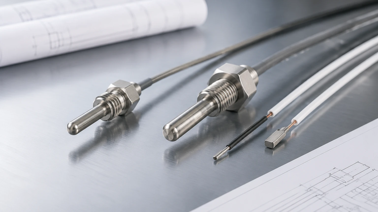
4. Environmental Compatibility: Consider the chemical nature of the fluid. For corrosive environments, the RTD must be housed in a suitable thermowell made of stainless steel, Hastelloy, or PTFE-coated materials.
Installation and Maintenance Guidelines
Proper installation is vital to ensure that the resistance temperature device provides a true representation of the process temperature.
Use of Thermowells
In most industrial applications, RTDs are not placed directly in the fluid. Instead, they are inserted into a thermowell. The thermowell protects the sensor from high pressures, high flow velocities, and corrosive chemicals. When installing, ensure there is a tight fit or use heat-conductive paste between the RTD probe and the thermowell wall to minimize thermal lag.
Immersion Depth
To prevent "stem conduction" (where heat travels along the sensor sheath to the outside environment, causing a false low or high reading), the sensor must be immersed deeply enough. A general rule of thumb is an immersion depth of at least 10 times the diameter of the sensor protection tube.
Wiring and Shielding
Since RTDs deal with relatively small changes in resistance, they are sensitive to electromagnetic interference (EMI). Always use shielded, twisted-pair wiring and ensure the shield is grounded at only one end (usually the controller side) to prevent ground loops.
Limitations and Common Risks
While highly accurate, RTDs are not suitable for every application. Engineers should be aware of the following limitations:
* Self-Heating: To measure resistance, a small current must be passed through the RTD. This current generates a tiny amount of heat. If the excitation current is too high (typically >1 mA), it can raise the temperature of the sensor element, leading to a measurement error.
* Vibration: In applications with extreme mechanical vibration, the fine wires in a wire-wound RTD can fatigue and break. Thin-film RTDs are generally more robust in these scenarios.
* Cost: RTDs are generally more expensive than thermocouples, especially when high-grade platinum or specialized thermowells are required.
* Temperature Ceiling: RTDs are generally limited to temperatures below 850°C. For applications exceeding this, such as furnace monitoring, thermocouples are usually the preferred choice.
Frequently Asked Questions (FAQs)
What is the difference between an RTD and a Thermocouple?
An RTD uses the change in electrical resistance of a metal to measure temperature and is generally more accurate and stable at lower temperatures. A thermocouple uses the voltage generated by the junction of two dissimilar metals (Seebeck effect) and is better suited for extremely high temperatures and rugged environments.
Why is Pt100 more common than Pt1000?
Pt100 has been the industrial standard for decades, meaning most legacy control systems and transmitters are designed specifically for its 100-ohm base resistance. Pt1000 is gaining popularity in battery-operated or low-power wireless sensors because its higher resistance allows for lower current consumption.
Can I use a 2-wire RTD for precise measurements?
It is not recommended for precise measurements unless the lead wires are extremely short (less than 1 meter). For most industrial processes, a 3-wire or 4-wire configuration is necessary to compensate for lead wire resistance.
How often should an RTD be calibrated?
In critical processes, annual calibration is standard. However, RTDs are known for their excellent long-term stability, often drifting less than 0.1°C per year in stable environments.
Conclusion
Understanding what is resistance temperature device technology is essential for any professional involved in industrial process control. These sensors provide the accuracy and repeatability required to maintain product quality and operational safety. Whether used as a standalone temperature monitor or as a compensation component in advanced level measurement systems, the RTD remains a fundamental tool in the modern industrial toolkit. For more information on how temperature sensing integrates with industrial automation, visit the Welk Main Page to explore comprehensive measurement solutions.