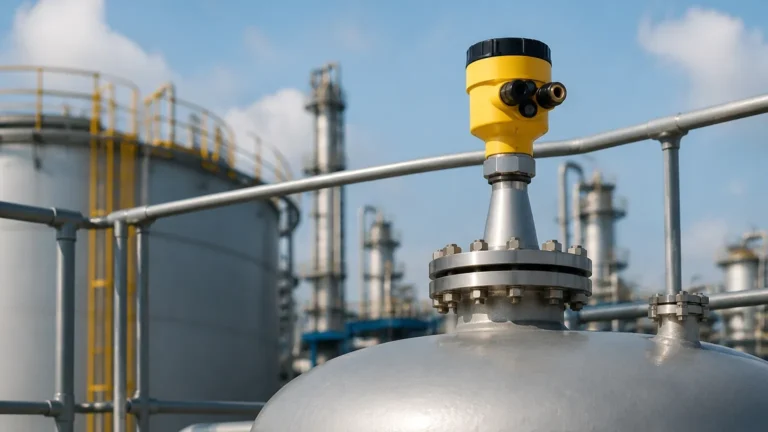
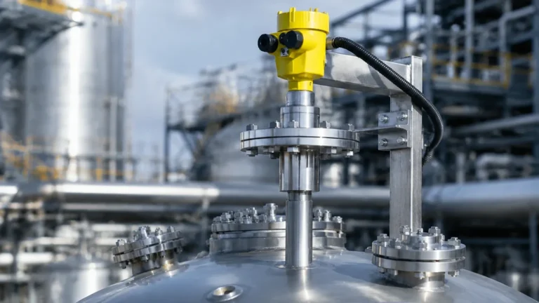
80ghz Radar Level Transmitter
80GHz Radar Level Transmitter: A Technical Engineering Guide to High-Frequency Level Measurement
In the landscape of industrial process automation, the accuracy and reliability of level measurement are critical to operational efficiency and safety. Among the various technologies available, the 80ghz radar level transmitter has emerged as a preferred solution for complex applications where traditional ultrasonic or lower-frequency radar sensors struggle. Utilizing Frequency Modulated Continuous Wave (FMCW) technology, these high-frequency instruments provide superior resolution and a narrow beam angle, making them indispensable in modern chemical processing, water treatment, and bulk solids storage.
As a professional manufacturer, Welk specializes in providing advanced Radar Level Meters that address the nuances of industrial environments. This guide explores the engineering principles, selection criteria, and installation best practices for 80GHz radar technology.
Understanding the Measurement Principle: 80GHz FMCW Technology
To effectively implement an 80ghz radar level transmitter, engineers must first understand the underlying physics of Frequency Modulated Continuous Wave (FMCW) measurement. Unlike pulsed radar, which measures the time-of-flight of a single microwave pulse, FMCW radar transmits a continuous signal with a frequency that increases linearly over time (a frequency sweep or "chirp").
The FMCW Process
1. Signal Transmission: The transmitter emits a continuous microwave signal. The frequency of this signal changes at a constant rate over a specific bandwidth.
2. Reflection: The signal travels to the surface of the medium (liquid or solid) and reflects back toward the sensor antenna.
3. Signal Processing: The instrument compares the frequency of the received signal with the frequency being transmitted at that exact moment. Because the transmitted frequency has changed during the signal's travel time, a frequency difference (the "beat frequency") is generated.
4. Distance Calculation: This beat frequency is directly proportional to the distance between the sensor and the material surface. Advanced digital signal processing (DSP) then converts this frequency into a precise distance measurement.
At 80GHz, the bandwidth available for the frequency sweep is significantly wider (often up to 4GHz or more) compared to 26GHz radar. This increased bandwidth allows for a much higher range resolution, enabling the sensor to distinguish between the material surface and nearby obstructions with millimeter precision.
Comparative Advantages: Why Choose 80GHz Over Lower Frequencies?
When selecting Radar Level Meters, engineers often compare 80GHz systems with legacy 6GHz or 26GHz models. The transition to higher frequencies offers several distinct technical advantages.
Narrow Beam Angle
The beam angle of a radar sensor is inversely proportional to its frequency and the size of its antenna. Because 80GHz has a very short wavelength (approximately 3.75 mm), it can produce a highly focused beam even with a small antenna. While a 26GHz radar might have a beam angle of 10° to 15°, an 80ghz radar level transmitter typically achieves a beam angle as narrow as 3°.
This narrow focus is critical when:
* Measuring in tall, narrow silos.
* Installing sensors in tanks with internal obstructions like agitators, heating coils, or ladders.
* Measuring through narrow nozzles or standpipes.
Enhanced Signal Sensitivity and Accuracy
High-frequency signals reflect more efficiently off various surfaces, including materials with low dielectric constants (εr). The 80GHz signal provides a stronger return echo from turbulent liquid surfaces or uneven solid piles, resulting in a higher signal-to-noise ratio. This translates to a standard accuracy of ±1 mm to ±2 mm, even over distances exceeding 30 meters (approx. 98 feet).
Smaller Process Connections
Due to the smaller antenna requirements, 80GHz transmitters can be fitted with process connections as small as 1 inch (G1" or 1" NPT). This simplifies retrofitting into existing tanks where larger flange openings are not available.
Selection Criteria and Technical Specifications
Choosing the right 80ghz radar level transmitter requires a thorough analysis of the process medium and the vessel geometry. The following table provides a general comparison of common radar configurations used in industrial settings.
| Specification | 80GHz FMCW Radar | 26GHz Pulse/FMCW Radar | 6GHz Pulse Radar |
| :— | :— | :— | :— |
| Typical Beam Angle | 3° – 6° | 8° – 20° | 20° – 30° |
| Measurement Range | Up to 120m (393 ft) | Up to 30m – 70m | Up to 30m |
| Accuracy | ±1 mm to ±2 mm | ±3 mm to ±5 mm | ±10 mm |
| Antenna Size | Small (Lens/Horn) | Medium to Large | Large |
| Sensitivity to Dust | Low (High Penetration) | Moderate | High |
| Internal Obstructions| Excellent Avoidance | Moderate Avoidance | Poor Avoidance |
Key Factors for Buyers to Confirm:
1. Dielectric Constant (εr): Materials with εr < 1.4 require high-sensitivity 80GHz units to ensure a reliable echo.
2. Process Temperature and Pressure: Ensure the lens material (typically PTFE or PEEK) and seals (FKM, FFKM) are compatible with the operating environment.
3. Output Protocol: Standard 4-20mA with HART is common, but RS485 Modbus or Profibus may be required for complex automation architectures.
Installation Guidelines and Engineering Constraints
Proper installation is paramount to the performance of an 80ghz radar level transmitter. Despite the narrow beam, certain physical constraints must be respected.
Nozzle Dynamics
The transmitter should be mounted such that the antenna extends slightly below the bottom of the nozzle. If the antenna is recessed deep within a narrow nozzle, internal reflections (ringing) can interfere with the signal. However, many 80GHz models feature "nozzle compensation" algorithms that allow for mounting in nozzles up to 500 mm (approx. 19.6 inches) long.
Avoidance of the Tank Center
For vessels with a torispherical or conical bottom, avoid mounting the sensor in the exact center of the tank. This prevents multiple reflections from the tank walls from converging and creating a false "ghost" echo at the sensor.
Obstruction Clearance
Maintain a clear path for the radar beam. While the 3° beam is narrow, it still expands over distance. At a distance of 10 meters (32.8 feet), a 3° beam has a diameter of approximately 520 mm (20.5 inches). Ensure no structural members or pipes enter this zone.
Alignment
For bulk solids, the angle of repose can cause the signal to reflect away from the sensor. Using an adjustable flange (swivel mount) allows the engineer to aim the 80ghz radar level transmitter at the material surface to maximize signal return.

Application-Specific Considerations: Solids vs. Liquids
Liquid Applications
In liquid tanks, 80GHz radar excels at measuring through foam and vapor. While heavy foam can attenuate any microwave signal, the high frequency of 80GHz allows it to penetrate light to medium foam layers more effectively than ultrasonic sensors. In the case of highly corrosive liquids, the non-contact nature of the radar, combined with a PTFE-sealed lens, ensures long-term durability without the risk of sensor degradation.
Solids and Powders
Measuring the level of powders (like cement, flour, or plastic pellets) presents challenges due to dust and uneven surfaces. The 80GHz signal has a shorter wavelength that interacts better with small particles, providing a consistent reflection even during filling cycles where dust clouds are prevalent. The high energy density of the narrow beam helps the signal penetrate heavy dust to reach the actual material surface.
Maintenance and Troubleshooting in Process Environments
One of the primary benefits of an 80ghz radar level transmitter is its low maintenance requirement, as it has no moving parts. However, certain conditions can still affect performance:
* Condensation and Buildup: While 80GHz radar is resilient, heavy condensation or material buildup on the lens can attenuate the signal. Many industrial units include an integrated air purge connection to keep the lens face clean in dusty or high-moisture environments.
* Signal Loss (LOE): If the device reports a "Loss of Echo," check for extreme turbulence, excessive foam, or an incorrect mounting angle. In many cases, adjusting the sensitivity or "false echo suppression" settings in the software can resolve the issue.
* Interference: While 80GHz is a regulated frequency for industrial level measurement, ensure that multiple radar units in close proximity are not aimed directly at one another, though the narrow beam makes this unlikely.
Procurement Checklist for International Buyers
When sourcing an 80ghz radar level transmitter for global projects, international buyers should verify the following technical and commercial details with the manufacturer:
1. Certifications: Does the device meet ATEX, IECEx, or SIL2 safety requirements for hazardous areas?
2. Housing Material: Is the housing aluminum with an epoxy coating, or is 316L stainless steel required for offshore or food-grade environments?
3. Configuration Tools: Is the device configurable via a local display, a smartphone app (Bluetooth), or a PC-based software tool (HART modem)?
4. OEM/ODM Flexibility: For large-scale integrators, can the manufacturer provide custom process connections or private-labeling services?
5. Documentation: Request full calibration reports and material certificates (e.g., 3.1 certificates) to ensure compliance with local engineering standards.
Frequently Asked Questions (FAQ)
Q: Can 80GHz radar measure through a plastic tank wall?
A: Yes, because microwaves can penetrate non-conductive materials like polyethylene or fiberglass. This allows for "non-invasive" measurement where the sensor is mounted outside the tank, looking through the top wall.
Q: Is 80GHz radar affected by temperature or pressure changes?
A: No. Unlike ultrasonic sensors, which depend on the speed of sound (which varies with air density), radar signals travel at the speed of light. Changes in tank pressure or temperature do not significantly affect the accuracy of the measurement.
Q: What is the minimum dielectric constant required for 80GHz radar?
A: Generally, these transmitters can measure materials with a dielectric constant as low as 1.4. For materials below this value, a stilling well or a guided wave radar might be considered, though 80GHz FMCW is often successful where other non-contact methods fail.
Q: How does 80GHz radar handle agitators?
A: The narrow beam angle usually allows the radar to be positioned to avoid the agitator blades. Additionally, the software includes a "masking" or "false echo suppression" feature that allows the transmitter to learn and ignore reflections from moving blades.
By selecting a high-quality 80ghz radar level transmitter, industrial facilities can achieve unprecedented levels of precision and reliability. Whether managing volatile chemicals or abrasive bulk solids, the focused energy and advanced signal processing of 80GHz technology provide a robust solution for the most demanding level measurement challenges.