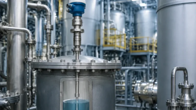
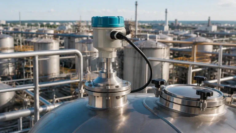
Vegaflex 81 Radar Level Transmitter
Vegaflex 81 Radar Level Transmitter: Engineering Principles and Application Guide
In the landscape of industrial process control, the accurate measurement of liquid levels and interfaces is critical for operational safety, inventory management, and process efficiency. The vegaflex 81 radar level transmitter represents a significant advancement in Guided Wave Radar (GWR) technology. Unlike traditional non-contact Radar Level Meters, which emit signals through the air, the Vegaflex 81 utilizes a physical probe to guide microwave pulses directly to the medium. This engineering approach provides distinct advantages in environments characterized by foam, steam, or turbulent surfaces.
This guide examines the technical foundations of the vegaflex 81 radar level transmitter, its selection criteria, and the practical installation requirements necessary for reliable industrial performance.
1. Measurement Principle: Time Domain Reflectometry (TDR)
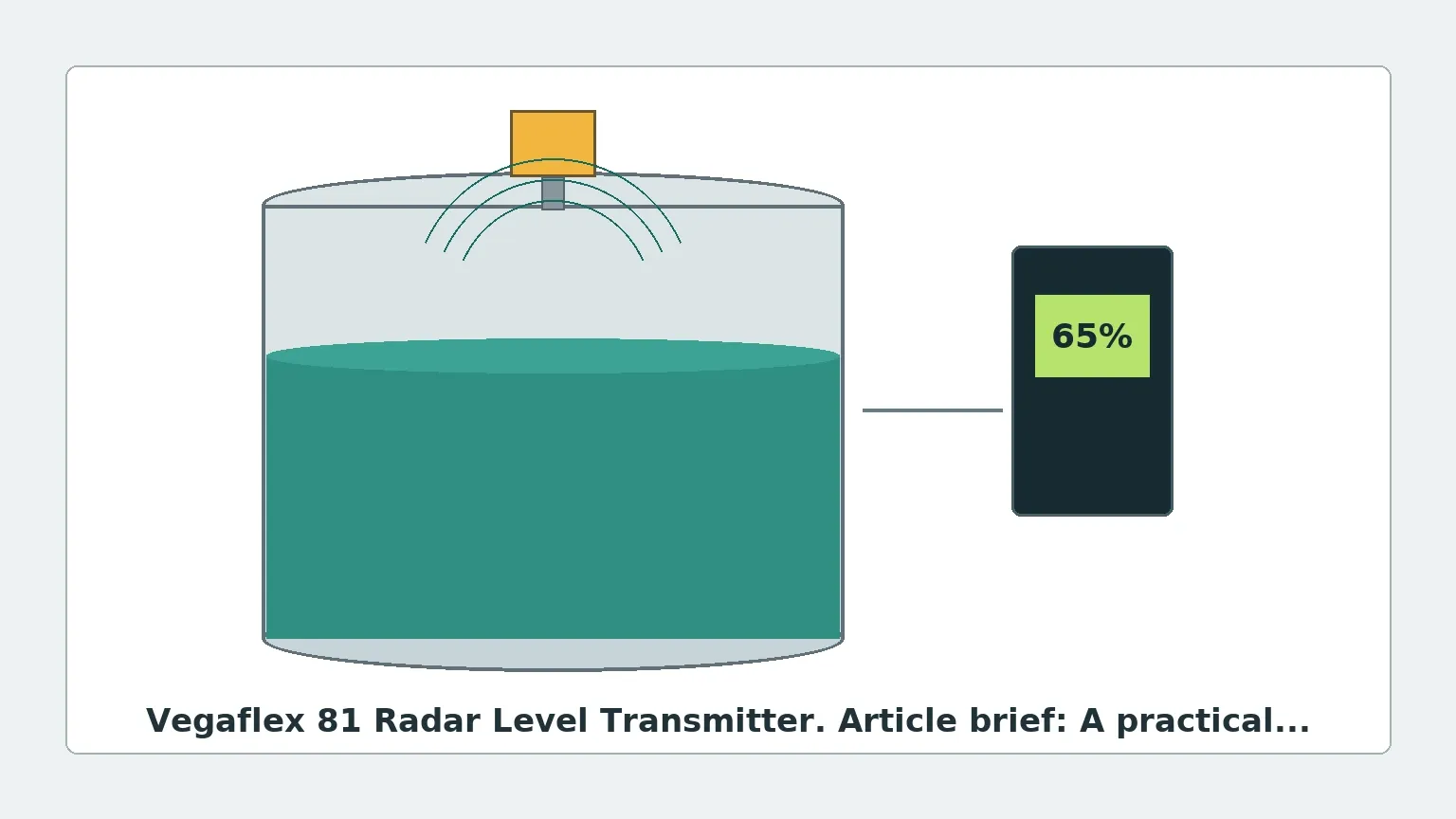
The vegaflex 81 radar level transmitter operates on the principle of Time Domain Reflectometry (TDR). This method involves sending high-frequency, low-energy microwave pulses along a mechanical waveguide (the probe).
The Signal Path
When these pulses reach the surface of the product being measured, the change in the dielectric constant ($ε_r$) between the upper medium (usually air or gas) and the process medium causes a partial reflection of the signal. The electronics within the transmitter housing measure the time-of-flight between the emission of the pulse and the reception of the reflected echo. Since the speed of light in a vacuum (and approximately in air) is a known constant, the distance to the product surface is calculated using the formula:
Distance = (Speed of Light × Time-of-Flight) / 2
Interface Measurement
One of the primary strengths of the vegaflex 81 radar level transmitter is its ability to measure interfaces. If the upper liquid layer has a low dielectric constant (e.g., oil) and the lower layer has a high dielectric constant (e.g., water), the microwave pulse will partially reflect off the first surface and continue through the upper liquid to reflect off the second surface. This allows for the simultaneous measurement of both the total level and the interface level within a single vessel.
2. Technical Specifications and Selection Criteria
Selecting the correct configuration for a vegaflex 81 radar level transmitter requires an understanding of the process environment. The device is designed for maintenance-free operation in liquids, but the physical probe must be matched to the chemical and physical properties of the medium.
Probe Types and Applications
| Probe Type | Best Use Case | Max. Measuring Range | Dielectric Constant (ε_r) |
| :— | :— | :— | :— |
| Cable (Exchangeable) | Tall tanks, silos, and deep sumps with low viscosity liquids. | Up to 75 m (246 ft) | ≥ 1.6 |
| Rod (Exchangeable) | Small vessels, agitated tanks, or corrosive liquids. | Up to 6 m (19.7 ft) | ≥ 1.6 |
| Coaxial | Low dielectric liquids, bypass pipes, or near-wall mounting. | Up to 6 m (19.7 ft) | ≥ 1.4 |
Process Limits
* Temperature: -40 °C to +200 °C (-40 °F to +392 °F).
* Pressure: -1 to +40 bar (-100 to +4000 kPa).
* Materials: Typically 316L stainless steel, with options for Hastelloy or PFA coatings for aggressive chemical resistance.
3. Comparison: Guided Wave vs. Non-Contact Radar
While both technologies fall under the umbrella of Radar Level Meters, the vegaflex 81 radar level transmitter offers specific benefits where non-contact sensors may struggle.
1. Surface Turbulence: Because the signal is guided by a probe, surface ripples or heavy agitation do not disperse the signal as easily as they would with non-contact radar.
2. Foam Suppression: GWR pulses can often penetrate layers of foam to reach the true liquid surface, whereas non-contact radar might reflect off the top of the foam.
3. Vessel Geometry: Non-contact radar requires a clear "line of sight." The vegaflex 81 can be used in narrow nozzles or tanks with internal obstructions, provided the probe does not make physical contact with those obstructions.
4. Vapor and Dust: High-density steam or dust clouds can attenuate non-contact signals. The guided path of the TDR pulse is significantly less affected by these atmospheric conditions.
4. Installation Considerations and Constraints
Correct installation is paramount to the accuracy of the vegaflex 81 radar level transmitter. Engineers must account for several physical factors during the design phase.
Dead Zones (Blocking Distances)
Every radar transmitter has a "dead zone" at the top and bottom of the probe where measurement is either impossible or inaccurate.
* Upper Dead Zone: Typically ranges from 50 mm to 250 mm (2 to 10 inches), depending on the probe type and the dielectric of the medium.
* Lower Dead Zone: Often occurs at the very tip of the probe, especially in media with low dielectric constants.
Mounting Position
* Distance from Wall: For rod and cable probes, a minimum distance of 300 mm (12 inches) from the tank wall is recommended to prevent signal interference. If the tank is plastic, the probe should be at least 500 mm from the wall.
* Nozzle Dimensions: The nozzle height should be kept as short as possible. If a long nozzle is required, a coaxial probe or a rod probe with a specific bypass pipe is preferred to avoid false reflections from the nozzle internal surface.
* Avoid Obstacles: The probe must not touch heating coils, ladders, or agitators. If movement is expected due to turbulence, the probe may need to be anchored at the bottom (using a weight or a centering disk).
Bypass and Stillpipes
In applications with extreme turbulence or very low dielectric constants, installing the vegaflex 81 radar level transmitter inside a bypass pipe or a stillpipe is an effective engineering solution. This creates a controlled environment that concentrates the microwave energy, effectively increasing the signal-to-noise ratio.
5. Application Risks and Limitations
Despite its versatility, the vegaflex 81 radar level transmitter has specific limitations:
* Build-up and Coating: While the TDR technology can compensate for thin films of liquid on the probe, heavy, conductive build-up (such as thick sludge or crystallizing salts) can cause signal attenuation or false high-level readings.
* Mechanical Stress: In high-flow environments, the lateral forces on a long rod or cable probe can lead to mechanical failure or damage to the tank internals. In these cases, a coaxial probe or a protective stillpipe is necessary.
* Dielectric Minimums: If the dielectric constant of the medium is extremely low (ε_r < 1.4), the reflected signal may be too weak for the transmitter to distinguish from background noise.
6. Buyer’s Checklist: Information for International Procurement
When sourcing a vegaflex 81 radar level transmitter for an industrial project, international buyers should confirm the following data points with the manufacturer to ensure compatibility:
1. Medium Properties: What is the dielectric constant? Is it corrosive, viscous, or prone to crystallization?
2. Vessel Specifications: What is the total height, nozzle diameter, and nozzle height? Are there internal obstructions?
3. Process Conditions: What are the maximum and minimum operating temperatures and pressures?
4. Output Requirements: Is a standard 4-20mA HART signal required, or is there a need for Foundation Fieldbus, Profibus PA, or Modbus?
5. Certifications: Does the site require ATEX/IECEx for hazardous zones, or SIL2/3 for functional safety systems?
7. Frequently Asked Questions (FAQ)
Q: Can the vegaflex 81 radar level transmitter be shortened in the field?
A: Yes, most cable and rod versions of the Vegaflex 81 are designed to be shortened by the user. After cutting the probe to the desired length, the device must be recalibrated via the integrated display or a PC-based adjustment tool to reflect the new probe length.
Q: Does the device require a ground reference?
A: For optimal performance, especially in plastic tanks, a metal flange or a reference plate is required to provide a proper launch surface for the microwave pulse.
Q: How does steam affect the measurement?
A: Steam has a higher dielectric constant than air. In high-pressure steam applications (such as boiler drums), the speed of the microwave pulse can slow down, leading to a "measured distance" error. For these specific cases, specialized versions with steam compensation are recommended.
Q: Is the vegaflex 81 suitable for bulk solids?
A: While the Vegaflex 81 can measure some solids, it is primarily optimized for liquids. For heavy bulk solids or powders where pull-down forces are high, the Vegaflex 82 is generally the preferred engineering choice due to its higher mechanical tensile strength.
Conclusion
The vegaflex 81 radar level transmitter is a robust solution for complex liquid level and interface challenges. By guiding the radar signal along a probe, it overcomes many of the environmental hurdles that affect standard non-contact Radar Level Meters. However, successful implementation depends on precise probe selection and adherence to installation geometry. When configured correctly, it provides a highly accurate, maintenance-free measurement that is essential for modern industrial automation.