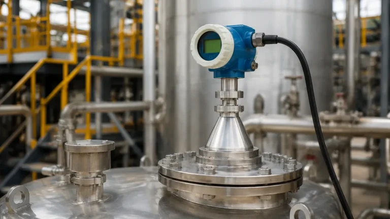
Dead Zone in Radar Level Transmitter
Dead Zone in Radar Level Transmitter: A Technical Engineering Guide
In the field of industrial process control, the accuracy of level measurement is paramount for safety, inventory management, and process efficiency. Among the various technologies available, non-contact radar has emerged as a gold standard due to its reliability in harsh environments. However, every instrument has physical and electronic limitations. One of the most critical factors for instrumentation engineers to understand is the dead zone in radar level transmitter applications.
This guide explores the technical nature of dead zones, the underlying measurement principles of Radar Level Meters, and practical strategies for mitigating measurement errors at the top of the tank.
Understanding Radar Level Measurement Principles
Before addressing the dead zone, it is essential to understand how radar sensors determine the distance to a liquid or solid surface. Industrial radar level transmitters generally operate using one of two primary methods: Pulse Radar (Time of Flight) or Frequency Modulated Continuous Wave (FMCW).
Pulse Radar (Time of Flight)
Pulse radar transmitters emit a short microwave pulse toward the product surface. The pulse reflects off the surface and returns to the sensor. The transmitter measures the time it takes for the pulse to travel to the surface and back (Time of Flight). Since the speed of electromagnetic waves is constant (the speed of light), the distance is calculated as:
Distance = (Speed of Light × Time of Flight) / 2
Frequency Modulated Continuous Wave (FMCW)
FMCW radar transmits a continuous signal with a constantly changing frequency (a frequency sweep). When the reflected signal is received, it is compared to the signal being transmitted at that exact moment. The difference in frequency (the "beat frequency") is directly proportional to the distance. FMCW is generally preferred for high-precision applications because it offers a better signal-to-noise ratio and higher resolution.
What is the Dead Zone in Radar Level Transmitter Technology?
The dead zone, also known as the "blind zone" or "upper blocking distance," refers to the area immediately below the radar antenna where the instrument cannot provide a reliable or accurate measurement. If the material level rises into this zone, the transmitter may output an error code, hold the last known valid value, or provide a false reading (often jumping to the very top or bottom of the range).
Why Does the Dead Zone Exist?
The existence of a dead zone in radar level transmitter units is primarily due to three factors:
1. Antenna Ringing (Pulse Radar): In pulse-based systems, the same antenna is often used for both transmitting and receiving. After the pulse is sent, the antenna continues to vibrate or "ring" for a few nanoseconds. During this time, the receiver cannot distinguish between the antenna's own vibration and a reflection from a very close surface.
2. Signal Processing Time: The electronics require a finite amount of time to switch from transmit mode to receive mode. Any reflection returning during this switching interval is lost.
3. Near-Field Interference (FMCW): In FMCW systems, although there is no "switching" time, the high energy of the outgoing signal can saturate the receiver if the reflection occurs too close to the antenna. Additionally, internal reflections within the nozzle or the antenna assembly itself can create a "noise floor" that masks the true level signal at close range.
Technical Comparison: Frequency and Dead Zone
The frequency of the radar signal significantly influences the size of the dead zone. Generally, higher-frequency radars (such as 80 GHz) have much smaller dead zones compared to lower-frequency units (6 GHz or 26 GHz).
| Radar Frequency | Typical Dead Zone | Best Use Case |
| :— | :— | :— |
| 6 GHz (C-Band) | 400 mm – 600 mm | Applications with heavy foam, steam, or extreme turbulence. |
| 26 GHz (K-Band) | 150 mm – 300 mm | General purpose liquid and solid measurement in medium-sized tanks. |
| 80 GHz (W-Band) | 0 mm – 50 mm | Small vessels, high-precision requirements, and narrow nozzles. |
*Note: While some 80 GHz manufacturers claim a "zero" dead zone, there is always a physical limit (often 10-50 mm) where accuracy begins to degrade due to the thickness of the antenna lens and near-field physics.*
Factors Affecting Dead Zone Performance
While the manufacturer specifies a nominal dead zone, real-world conditions can extend this area. Engineers must account for the following variables during the design phase:
1. Nozzle Geometry
The mounting nozzle is a frequent source of measurement interference. If a radar is mounted on a tall, narrow nozzle, the signal may reflect off the internal walls of the pipe. These reflections can interfere with the signal processing, effectively increasing the dead zone in radar level transmitter setups to the full length of the nozzle plus the manufacturer’s specified distance.
2. Dielectric Constant (εr)
The reflectivity of the material depends on its dielectric constant. Materials with low dielectric constants (like oils or plastic pellets) reflect less energy. If a low-dielectric material enters the near-field of the radar, the weak reflection may be completely lost in the "noise" of the antenna ringing, whereas a high-dielectric material (like water) might still be detectable closer to the sensor.
3. Surface Turbulence
Agitators or boiling liquids create surface turbulence. When the liquid level is near the dead zone, the combination of signal saturation and a non-perpendicular surface can cause the radar to lose its "lock" on the level much sooner than it would with a calm surface.
Installation Considerations to Mitigate Dead Zones
To ensure the Radar Level Meters perform accurately at the top of the tank, follow these installation best practices:
* Mounting Height: If the process requires the tank to be filled to the very top, the radar should be mounted on a standpipe or an extension to lift the antenna's reference point above the maximum possible liquid level. This ensures the maximum level remains outside the dead zone.
* Nozzle Design: Ensure the antenna extends slightly past the bottom of the mounting nozzle. If the antenna is recessed inside the nozzle, the "ringing" effect is amplified by the pipe walls.
* Clearance: Maintain a clear "cone of vision." Any internal obstructions (ladders, pipes, or heating coils) near the top of the tank can create parasitic reflections that the radar might confuse with the product level, especially near the dead zone.
* Stillpipes and Bypass Chambers: For applications where the dead zone or surface turbulence is a major concern, installing the radar in a stillpipe or a side-mounted bypass chamber can stabilize the signal and allow for more precise calibration of the upper range.

Practical Engineering Checklist for Selection
When specifying a radar level transmitter, international buyers and engineers should confirm the following data points with the manufacturer:
1. What is the minimum blocking distance? (Confirm if this is measured from the flange face or the antenna tip).
2. What is the recommended nozzle height and diameter?
3. Does the software allow for "False Echo Suppression"? This feature allows the transmitter to "learn" the reflections from the nozzle and ignore them, which can help optimize performance near the dead zone.
4. How does the transmitter behave upon entering the dead zone? Can the output be configured to "Fail High" (22mA) or "Fail Low" (3.6mA)?
Limitations and Risks
Ignoring the dead zone in radar level transmitter selection can lead to several industrial risks:
* Overfill Accidents: If the radar loses signal at the top of the tank and the system assumes the level is lower than it actually is, an overfill may occur. This is a significant safety and environmental risk in chemical and oil & gas industries.
* Pump Damage: In some logic configurations, a loss of signal might trigger a pump-down sequence or, conversely, prevent a pump from stopping, leading to dry running.
* Inaccurate Inventory: In high-value liquid storage, the top 300 mm of a tank often represents a significant volume. If this area cannot be measured, inventory reconciliation becomes impossible.
Frequently Asked Questions (FAQs)
Q: Can I calibrate the dead zone out of the transmitter?
A: No. The dead zone is a physical limitation of the electromagnetic physics and electronic switching speeds. You can configure the transmitter to ignore signals within that zone, but you cannot make the sensor measure accurately within it.
Q: Does Guided Wave Radar (GWR) have a dead zone?
A: Yes, GWR also has an upper dead zone (often called the transition zone). However, because the signal is contained along a probe, the dead zone is typically more predictable than in non-contact radar, though it is still influenced by the mounting configuration.
Q: How does an 80 GHz radar reduce the dead zone?
A: 80 GHz radars use a shorter wavelength, which allows for smaller antenna components and more focused beams. This reduces the "ringing" time and minimizes reflections from the nozzle walls, allowing the sensor to process reflections that are much closer to the lens.
Conclusion
Understanding the dead zone in radar level transmitter applications is a fundamental requirement for successful level automation. By selecting the appropriate frequency—such as the high-precision 80 GHz models found in modern Radar Level Meters—and adhering to strict installation guidelines regarding nozzle height and tank geometry, engineers can ensure reliable measurement across the entire vessel height. Always consult the technical datasheet for the specific "Upper Blocking Distance" and ensure that your maximum process level never encroaches upon this critical boundary.