Dielectric Constant for Radar Level Transmitter
Dielectric Constant for Radar Level Transmitter: An Engineering Guide
In the field of industrial process automation, selecting the correct instrumentation requires a deep understanding of the physical properties of the media being measured. Among these properties, the dielectric constant ($ε_r$) stands as the most critical parameter when specifying Radar Level Meters. Whether a facility is managing volatile hydrocarbons, corrosive chemicals, or bulk solids, the dielectric constant for radar level transmitter performance determines the reliability of the signal and the overall accuracy of the system.
This guide provides a comprehensive technical analysis of how dielectric properties influence radar measurement, the differences between non-contact and contact-based radar technologies, and practical installation strategies for challenging low-dielectric environments.
Understanding the Role of Dielectric Constant in Radar Measurement
Radar level measurement operates on the Time-of-Flight (ToF) principle. The instrument emits a high-frequency electromagnetic pulse (typically in the microwave spectrum) toward the surface of the material. When this pulse hits the media, a portion of the energy is reflected back to the sensor. The transmitter calculates the distance based on the time interval between the emission and the reception of the reflected signal.
The Physics of Reflection
The dielectric constant for radar level transmitter applications, also known as relative permittivity, is a measure of a material's ability to store electrical energy in an electric field. In the context of radar, it defines how much of the electromagnetic energy will be reflected at the interface between the air (or vapor space) and the process media.
The reflection coefficient ($R$) can be simplified by the following formula:
$$R = \frac{\sqrt{ε_r} – 1}{\sqrt{ε_r} + 1}$$
Where:
* $R$ is the portion of the signal reflected.
* $ε_r$ is the dielectric constant of the media.
From this relationship, it is evident that materials with a high dielectric constant, such as water ($ε_r ≈ 80$), produce a very strong reflection, making them easy to measure. Conversely, materials with a low dielectric constant, such as liquid nitrogen ($ε_r ≈ 1.4$) or certain dry powders, reflect very little energy, requiring more sensitive electronics and specialized antenna designs.
How Dielectric Constant Affects Reflection Strength
When specifying Radar Level Meters, engineers must categorize the media based on its reflectivity. If the dielectric constant is too low, the radar signal may pass through the material rather than reflecting off the surface. This can lead to the "bottom echo" effect, where the radar detects the bottom of the tank instead of the liquid level.
High Dielectric Media (ε_r > 10)
Materials like water-based solutions, acids, and alkalis fall into this category. These substances provide a clear, robust return signal. Even in the presence of surface turbulence or foam, the high reflectivity usually ensures a stable measurement.
Medium Dielectric Media (ε_r 3 to 10)
This category includes many alcohols, some oils, and granular solids. While the signal is weaker than water, standard non-contact radar units can typically handle these applications provided the antenna is sized correctly and the surface is relatively calm.
Low Dielectric Media (ε_r < 3)
Hydrocarbons, liquefied gases, and dry bulk solids often have very low dielectric constants. For these materials, the choice of the dielectric constant for radar level transmitter technology becomes critical. Without the right configuration, the signal-to-noise ratio (SNR) may drop below the threshold required for a reliable reading.
Comparing Radar Technologies Based on Media Dielectrics
There are two primary types of radar technology used in industrial level measurement: Non-Contact Radar and Guided Wave Radar (GWR). Each interacts differently with the dielectric properties of the media.
Non-Contact Radar (FMCW and Pulse)
Non-Contact Radar Level Meters emit signals through the air. Modern 80 GHz transmitters have significantly improved the ability to measure low-dielectric materials by focusing the beam into a narrow angle, thereby increasing the energy density hitting the surface. However, for extremely low $ε_r$ fluids, the signal may still be insufficient if the surface is agitated.
Guided Wave Radar (GWR)
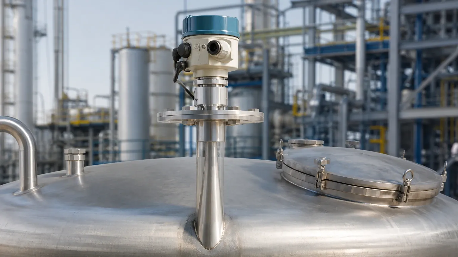
Guided Wave Radar uses a physical probe (cable or rod) to guide the microwave pulse directly to the media. Because the energy is concentrated around the probe rather than spreading through the air, GWR is far more efficient at detecting low-dielectric surfaces. GWR is often the preferred choice for media with $ε_r$ as low as 1.4.
| Feature | Non-Contact Radar (80 GHz) | Guided Wave Radar (GWR) |
| :— | :— | :— |
| Min. Dielectric (ε_r) | Typically ≥ 1.6 | Typically ≥ 1.4 |
| Surface Turbulence | Sensitive | Highly Resistant |
| Internal Obstructions | Requires clear path | Unaffected (if away from probe) |
| Maintenance | Low (no contact) | Moderate (probe cleaning) |
Dielectric Constant Reference Table for Industrial Media
To assist in the selection of Radar Level Meters, the following table lists common industrial substances and their approximate dielectric constants at room temperature (20°C).
| Material | Dielectric Constant (ε_r) | Reflectivity Category |
| :— | :— | :— |
| Deionized Water | 80 | Excellent |
| Ethanol | 24 | Good |
| Ammonia (Anhydrous) | 15 – 25 | Good |
| Cement (Dry Powder) | 4 – 6 | Moderate |
| Diesel Fuel | 2.1 | Low |
| Gasoline | 2.0 | Low |
| Propane (Liquid) | 1.6 | Very Low |
| Teflon (PTFE) | 2.0 | Low |
| Polyethylene Pellets | 1.5 | Very Low |
*Note: Dielectric constants can vary based on temperature and moisture content. For instance, dry sand has a low ε_r, but wet sand has a significantly higher value due to the presence of water.*
Overcoming Challenges with Low Dielectric Constant Media
When the dielectric constant for radar level transmitter applications is below 2.0, engineers must employ specific strategies to ensure measurement integrity.
1. Stilling Wells and Coaxial Probes
For non-contact radar, installing the sensor inside a stilling well (a vertical pipe) can help. The pipe acts as a waveguide, preventing the signal from dispersing and shielding the surface from turbulence. For GWR, a coaxial probe design provides the highest sensitivity, as it contains the electromagnetic field entirely within the outer tube, making it ideal for low-dielectric liquids like propane or hexane.
2. Interface Measurement
Radar is uniquely capable of measuring the interface between two liquids (e.g., oil and water). This is possible when the upper layer has a low dielectric constant and the lower layer has a high dielectric constant. The radar pulse passes through the low-$ε_r$ upper layer (reflecting only a small portion) and then reflects strongly off the high-$ε_r$ lower layer.
3. Signal Processing and Sensitivity Thresholds
Modern transmitters allow for the adjustment of the "threshold" or "gain." By increasing the sensitivity, the device can detect the faint echoes from low-dielectric materials. However, this also increases the risk of detecting "noise" from tank walls or internal structures, necessitating careful mapping of false echoes.
Installation Best Practices for Low-Reflectivity Applications
Correct installation is paramount when dealing with a challenging dielectric constant for radar level transmitter setups. Follow these engineering guidelines to optimize performance:
* Avoid Nozzle Interference: Ensure the radar beam does not hit the edges of the mounting nozzle. For low-dielectric media, any signal lost to nozzle interference significantly degrades the accuracy.
* Perpendicular Alignment: The antenna must be mounted perfectly perpendicular to the liquid surface. A tilt of even a few degrees can cause the reflected signal to miss the receiver, especially when the reflection is already weak.
* Avoid Obstructions: Agitators, ladders, and heating coils create false reflections. While software can "mask" these, the best practice is to provide a clear line of sight to the material surface.
* Consider Vapor Effects: High-pressure vapors (such as high-pressure steam) can change the propagation speed of the radar signal, effectively changing the apparent dielectric of the gas space. This requires compensation in the transmitter settings to maintain accuracy.
Critical Factors for International Procurement
For B2B buyers and engineers sourcing level instrumentation, the dielectric constant should be the first piece of information provided to the manufacturer. When requesting a quote for Radar Level Meters, ensure the following factual boundaries are confirmed:
1. Minimum Dielectric Constant: Confirm the media's ε_r at the process operating temperature.
2. Process Conditions: Specify maximum pressure (in bar or MPa) and temperature (in °C). High temperatures can lower the dielectric constant of some liquids.
3. Tank Geometry: Provide the height of the tank and the presence of any internal obstructions.
4. Accuracy Requirements: Determine if the application requires standard industrial accuracy (±3 mm to ±5 mm) or high-precision custody transfer accuracy (±1 mm).
Frequently Asked Questions (FAQ)
Q: Can a radar level transmitter measure media with a dielectric constant of 1.2?
A: Standard radar units typically struggle below 1.4. For values as low as 1.2, specialized high-sensitivity GWR or non-contact units with large parabolic antennas and advanced signal processing are required. Stilling wells are almost always necessary in these cases.
Q: Does the dielectric constant change with temperature?
A: Yes. For most liquids, the dielectric constant decreases as temperature increases. This is because higher thermal energy disrupts the alignment of molecular dipoles. It is vital to use the ε_r value at the maximum operating temperature during the design phase.
Q: Why is 80 GHz radar better for low dielectric materials than 26 GHz?
A: 80 GHz radar has a much shorter wavelength, which allows for a smaller antenna to produce a much narrower beam. This concentration of energy results in a stronger return signal from the surface, even if the material has a low dielectric constant.
Q: How does moisture affect the dielectric constant of solids?
A: Moisture significantly increases the dielectric constant. For example, dry grain might have an ε_r of 2.5, while damp grain could be 10 or higher. If the moisture content fluctuates, the radar must be calibrated for the lowest expected dielectric to ensure it never loses the signal.
By carefully considering the dielectric constant for radar level transmitter selection, industrial operators can avoid common pitfalls such as signal loss and inaccurate readings. For complex applications involving low-reflectivity media, consulting with a professional manufacturer like Welk ensures that the chosen Radar Level Meters are perfectly matched to the specific process requirements.
Download Dielectric Constant for Radar Level Transmitter as a PDF