Rosemount Radar Level Transmitter
Rosemount Radar Level Transmitter: A Technical Engineering Guide to Selection and Application
In the landscape of industrial process automation, the accurate measurement of liquid and solid levels is fundamental to operational safety, inventory management, and process efficiency. Among the various technologies available, radar-based systems have emerged as the gold standard for challenging environments. Specifically, the rosemount radar level transmitter series has set significant benchmarks for reliability in industries ranging from oil and gas to chemical processing and water treatment.
This guide provides a comprehensive technical overview of radar level measurement principles, the specific characteristics of Rosemount’s technology, and the critical engineering factors involved in selecting and installing Radar Level Meters for industrial applications.
1. Understanding Radar Level Measurement Principles
Before selecting a specific transmitter, it is essential to understand the physics of how radar energy interacts with process media. Radar level transmitters operate on the Time-of-Flight (ToF) principle, where the instrument measures the time it takes for an electromagnetic pulse to travel from the sensor to the product surface and back.
Frequency Modulated Continuous Wave (FMCW) vs. Pulsed Radar
Modern high-performance transmitters, such as the Rosemount 5408, typically utilize Frequency Modulated Continuous Wave (FMCW) technology. Unlike traditional pulsed radar, which sends a single burst of energy and waits for the return, FMCW transmits a continuous signal with a constantly changing frequency.
The difference between the transmitted frequency and the received frequency (the "beat frequency") is directly proportional to the distance. This method provides a significantly higher signal-to-noise ratio, allowing the device to distinguish the true material surface from foam, agitation, or internal tank obstructions.
Guided Wave Radar (GWR) vs. Non-Contacting Radar
Radar technology is generally divided into two categories:
1. Non-Contacting Radar: The signal is emitted through an antenna (horn, parabolic, or lens) and travels through the vapor space. This is ideal for corrosive media or applications where the sensor should not touch the product.
2. Guided Wave Radar (GWR): The signal travels along a physical probe (cable or rod) immersed in the medium. GWR is highly effective for low dielectric liquids and applications with heavy turbulence or narrow nozzles, as the probe concentrates the energy.
2. Technical Specifications and Selection Criteria
Choosing the correct rosemount radar level transmitter requires an analysis of the process medium’s physical properties and the vessel's geometry. The following table outlines the primary selection parameters for the most common industrial models.
Selection Comparison Table
| Feature | Rosemount 5408 (Non-Contact) | Rosemount 5300 (Guided Wave) | Rosemount 3408 (Non-Contact) |
| :— | :— | :— | :— |
| Measurement Principle | 24 GHz FMCW | Time Domain Reflectometry (TDR) | 80 GHz FMCW |
| Standard Accuracy | ±2 mm (0.08 in) | ±2 mm (0.08 in) | ±2 mm (0.08 in) |
| Maximum Range | 40 m (131 ft) | 50 m (164 ft) | 30 m (98 ft) |
| Operating Temp. | -60°C to +250°C | -196°C to +400°C | -40°C to +150°C |
| Max Pressure | 100 bar (1450 psi) | 345 bar (5000 psi) | 25 bar (362 psi) |
| Min. Dielectric ($\\epsilon_r$) | > 1.2 | > 1.4 (lower with TBF) | > 1.2 |
The Role of the Dielectric Constant ($\\epsilon_r$)
The dielectric constant of the material is the most critical factor in radar measurement. It determines how much energy is reflected back to the transmitter. Water has a high dielectric ($\\epsilon_r \\approx 80$), providing a very strong reflection. Conversely, hydrocarbons and oils often have low dielectrics ($\\epsilon_r < 2.5$), which may require the use of Guided Wave Radar or high-sensitivity FMCW non-contacting units to ensure signal stability.
3. Installation Considerations and Constraints
Even the most advanced rosemount radar level transmitter will fail to perform if installation best practices are ignored. Radar waves behave similarly to light; they travel in straight lines and can be reflected by any metallic object in their path.
Nozzle Geometry and Placement
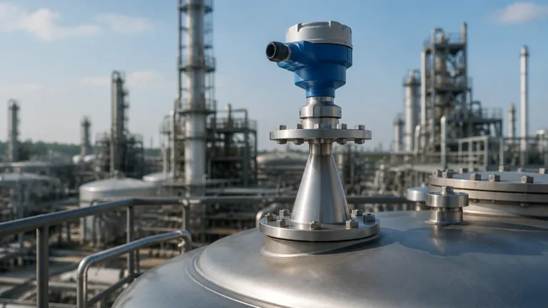
* Nozzle Height and Diameter: For non-contacting radar, the antenna should ideally extend slightly below the nozzle to prevent "ringing" or internal reflections within the nozzle neck. A 1:1 ratio of nozzle diameter to height is generally recommended.
* Wall Interference: The transmitter should be mounted at least 200 mm (8 inches) away from the tank wall to avoid side-lobe reflections. However, it should not be mounted in the exact center of a domed tank, as this can create a "parabolic mirror" effect that focuses unwanted noise back to the sensor.
Obstruction Management
Internal structures such as heating coils, agitators, and ladders can create "false echoes." While modern software can map out these echoes (False Echo Suppression), it is always better to install the device in a clear "line of sight" to the product surface. If an agitator is present, the transmitter should be configured with a software filter to ignore intermittent signals caused by the moving blades.
Stilling Wells and Bypass Pipes
In applications involving heavy foam or extreme turbulence, installing the radar inside a stilling well or a bypass pipe is often necessary. This provides a calm surface for measurement and can also amplify the signal for low dielectric fluids. When using a stilling well, the pipe must be smooth and free of burrs or misaligned joints.
4. Application Engineering: Where to Use Which Technology
Oil & Gas: High Pressure and Interface
In the oil and gas sector, the Rosemount 5300 series (GWR) is frequently used for interface measurement—detecting the boundary between oil and water. Because the radar signal can partially pass through the upper low-dielectric layer (oil) and reflect off the high-dielectric layer (water), it provides a simultaneous reading of both levels.
Chemical Processing: Corrosive Environments
For aggressive chemicals, non-contacting Radar Level Meters equipped with PTFE-faced seal antennas are preferred. This ensures that no metallic parts are exposed to the process, reducing the risk of corrosion and instrument failure.
Solids and Powders
Measuring solids (grain, plastic pellets, cement) presents unique challenges such as dust and uneven surfaces. High-frequency 80 GHz transmitters are often chosen here because their narrow beam angle (as small as 3 degrees) allows them to avoid the sloping sides of silos and focus on the material surface.

5. Limitations and Application Risks
While highly versatile, radar technology is not a universal solution. Engineers must be aware of the following limitations:
1. Heavy Foam: While FMCW radar can penetrate light foam, extremely dense, thick foam (like shaving cream) can absorb the radar signal entirely, leading to a "Loss of Echo" (LoE) error.
2. Vacuum Conditions: While radar works in a vacuum (unlike ultrasonic sensors which require a medium for sound travel), the mechanical seals and flanges must be rated for vacuum service to prevent air ingress.
3. Condensation and Buildup: Heavy condensation on the antenna can attenuate the signal. In these cases, antennas with integrated air purge systems or specialized "drip-off" lens designs should be used.
6. Frequently Asked Questions (FAQ)
Q: Does the Rosemount radar level transmitter require periodic calibration?
A: Unlike hydrostatic pressure transmitters, radar units do not suffer from "drift." Once the initial calibration (mapping the tank) is performed, the device typically does not require recalibration unless the process medium or tank internal structure changes significantly.
Q: Can I use a radar transmitter to measure the level of a solid and a liquid in the same tank?
A: Yes, but the configuration must be adjusted. Non-contacting radar is generally better for solids, while GWR is superior for liquid-liquid interfaces.
Q: What is the difference between 2-wire and 4-wire radar transmitters?
A: 2-wire devices are loop-powered (the same two wires carry the 4-20mA signal and the power), which simplifies wiring. 4-wire devices have separate power and signal lines, allowing for higher power consumption, which is sometimes needed for very long-range measurements or intensive signal processing.
Q: How does temperature affect radar accuracy?
A: Radar waves travel at the speed of light, which is virtually unaffected by changes in air temperature, pressure, or vapor composition. This makes radar much more accurate than ultrasonic technology in high-temperature applications.
7. Conclusion for International Buyers
When procuring a rosemount radar level transmitter, it is vital to provide the manufacturer or supplier with a complete process data sheet. This should include the minimum and maximum temperature/pressure, the dielectric constant of the medium, the tank height, and a detailed drawing of the mounting nozzle.
By following these engineering boundaries and selection criteria, process facilities can ensure long-term measurement stability and reduced maintenance costs. For further technical comparisons on various sensing technologies, reviewing modern Radar Level Meters options can provide additional insights into cost-effective alternatives for standard industrial applications.