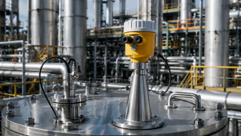
Dual Head Radar Level Transmitter
Dual Head Radar Level Transmitter: Engineering Principles and Application Guide
In the landscape of industrial process automation, the demand for high-reliability level measurement has led to the evolution of sophisticated sensing technologies. Among these, the dual head radar level transmitter represents a specialized configuration designed to address the stringent requirements of safety-instrumented systems (SIS), redundant process monitoring, and complex installation environments like bypass chambers. This guide examines the technical foundations of Radar Level Meters, the specific advantages of dual-head configurations, and the engineering criteria essential for successful deployment in B2B industrial settings.
1. Fundamental Measurement Principles
Before selecting a dual head radar level transmitter, it is critical to understand the underlying physics of radar-based level sensing. Industrial radar meters generally operate on two primary principles: Pulse Radar (Time of Flight) and Frequency Modulated Continuous Wave (FMCW).
1.1 Time of Flight (ToF) / Pulse Radar
Pulse radar transmitters emit short microwave pulses toward the surface of the medium. These pulses travel at the speed of light, reflect off the product surface due to the change in dielectric constant, and return to the receiver. The transmitter measures the time elapsed between emission and reception to calculate the distance.
1.2 Frequency Modulated Continuous Wave (FMCW)
FMCW radar emits a continuous signal with a constantly changing frequency (a frequency sweep). The reflected signal is received and compared to the signal being emitted at that exact moment. The frequency difference between the transmitted and received signals is directly proportional to the distance to the product surface. FMCW is generally preferred for high-precision applications and environments with significant vapor or turbulence because it provides a higher signal-to-noise ratio.
1.3 The "Dual Head" Configuration
In industrial instrumentation, a "dual head" or dual-chamber radar transmitter typically refers to one of two engineering designs:
1. Dual-Chamber Electronics: A single sensor head with two separate compartments—one for the electronic processing unit and another for the wiring/terminal block. This protects the electronics from moisture or corrosive gases during installation and maintenance.
2. Redundant Dual-Sensor Systems: Two independent radar sensor modules integrated into a single process connection or mounted on a shared bypass chamber. This is common in SIL2/SIL3 (Safety Integrity Level) environments where a failure of one sensor must not lead to a loss of monitoring.
2. Technical Selection Criteria
Selecting the correct radar level meters requires an analysis of the process medium, the vessel geometry, and the required accuracy. For a dual head radar level transmitter, the following parameters are authoritative:
2.1 Frequency Range
* 26 GHz (K-band): Suitable for most standard liquid applications. It offers a balance between beam angle and the ability to penetrate light foam or dust.
* 80 GHz (W-band): Features a much narrower beam angle (often as small as 3°). This is ideal for tall, narrow tanks or vessels with internal obstructions (agitators, heating coils) where a dual-head setup might otherwise face interference.
2.2 Dielectric Constant (εr)
The reflectivity of the radar signal depends on the dielectric constant of the medium. Materials with low εr (like liquefied gases or hydrocarbons) reflect less energy, requiring high-sensitivity FMCW transmitters. Water-based liquids (high εr) are much easier to detect.
2.3 Process Conditions
* Temperature: Standard units operate up to 150°C, while specialized high-temperature versions with cooling fins can withstand up to 450°C.
* Pressure: Ratings typically range from vacuum to 4 MPa (40 bar), though high-pressure flanges can extend this to 16 MPa.
3. Comparison of Radar Technologies
The following table provides a selection reference for different radar configurations used in industrial environments.
| Feature | 26 GHz Pulse Radar | 80 GHz FMCW Radar | Dual Head / Redundant Radar |
| :— | :— | :— | :— |
| Measurement Range | Up to 30m | Up to 120m | Up to 100m |
| Accuracy | ±3 mm to ±5 mm | ±1 mm | ±2 mm |
| Beam Angle | 8° – 20° | 3° – 8° | Dependent on sensor heads |
| Application | Standard storage tanks | Narrow vessels / Agitators | Safety-critical / SIL applications |
| Process Resistance | Moderate | High | Very High (Redundancy) |
| Cost Profile | Economical | Mid-range | High |
4. Engineering and Installation Considerations
Successful implementation of a dual head radar level transmitter depends heavily on physical installation geometry. Improper mounting is the leading cause of signal loss or "false echoes."
4.1 Nozzle Geometry
The mounting nozzle should be as short as possible. For dual-head systems, the nozzle diameter must accommodate the antenna type without causing internal reflections. If the nozzle is too long, the radar signal may reflect off the nozzle walls before reaching the process medium.
4.2 Beam Path and Obstructions
The "keep-out zone" or signal beam must remain clear of obstructions. When using a dual-head system for redundancy, engineers must ensure that the two signals do not interfere with each other. This is often managed by using different frequencies or by staggering the pulse timing.
4.3 Bypass Chambers and Stillpipes
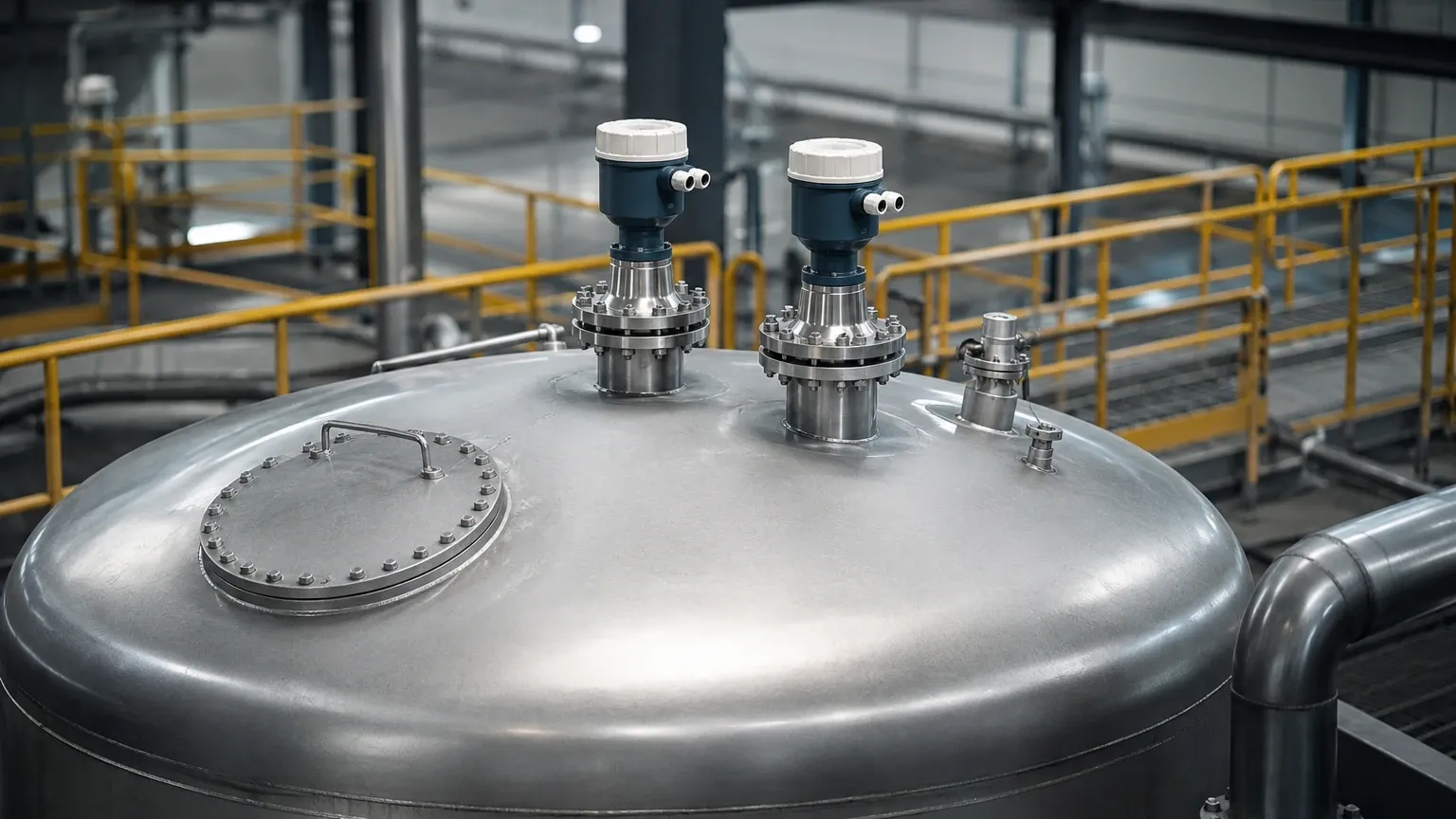
In applications involving boiling surfaces or heavy foam, radar transmitters are often installed in bypass chambers (side-mounted pipes). A dual head radar level transmitter can be mounted at the top of a bypass to provide redundant level data. The interior of the pipe must be smooth to prevent signal scattering.
4.4 Orientation and Polarization
Radar waves are polarized. Rotating the transmitter head can sometimes eliminate interference from tank walls or internal structures. In dual-head setups, proper orientation ensures that the secondary sensor does not receive the reflected signal intended for the primary sensor.
5. Industrial Applications
5.1 Chemical and Petrochemical
In volatile organic compound (VOC) storage, dual-head transmitters provide a layer of protection. If one electronic module fails due to a power surge or component aging, the second module continues to transmit 4-20mA or HART data to the control room, preventing overfill accidents.
5.2 Water and Wastewater Treatment
For large-scale desalination or wastewater processing, radar is preferred over ultrasonic sensors because it is unaffected by air temperature fluctuations, vacuum, or steam. Dual-head configurations are often used in primary intake wells where reliability is paramount for flood prevention.
5.3 Power Generation
In boiler drum level measurement or condensate tank monitoring, high temperatures and pressures are constant. Dual-head radar systems allow for maintenance on the electronic components without breaching the pressure vessel, as the electronics are often housed in a separate, dry chamber.
6. Limitations and Risks
While highly versatile, radar technology has specific limitations that engineers must account for:
* Heavy Foam: Extremely dense, thick foam can absorb radar signals entirely, leading to a "loss of echo." In these cases, guided wave radar (GWR) may be a more appropriate choice than non-contact radar.
* Extremely Low Dielectric Media: For media with εr < 1.4, the reflection may be too weak for standard non-contact radar. High-power FMCW units or stilling wells are required to concentrate the signal.
* Crystallization and Coating: If the process medium tends to crystallize or coat the antenna, the signal will attenuate. While some dual-head designs include "air purge" connections to clean the antenna, heavy buildup will eventually require manual cleaning.
7. Frequently Asked Questions (FAQ)
Q: Can a dual head radar level transmitter measure the interface between two liquids?
A: Standard non-contact radar is primarily designed for the top surface level. For interface measurement (e.g., oil over water), Guided Wave Radar (GWR) is typically required, as it can track the signal reflection from the interface layer.
Q: What is the benefit of a dual-chamber housing?
A: It separates the field wiring from the sensitive microprocessor electronics. This prevents environmental contaminants (moisture, dust) from entering the electronics compartment during installation or when the cover is removed for troubleshooting.
Q: How does 80 GHz technology improve dual-head performance?
A: The 80 GHz frequency allows for smaller antenna sizes and a much narrower beam. This makes it easier to fit two sensors near each other or to install the transmitter on small nozzles without the beam hitting the nozzle wall.
Q: Is periodic recalibration necessary?
A: Radar transmitters are generally drift-free because they rely on the speed of light and stable quartz oscillators. However, periodic verification is recommended in safety-critical applications to ensure no physical antenna fouling or scaling has occurred.
8. Conclusion for International Buyers
When sourcing a dual head radar level transmitter for international projects, it is essential to confirm the following with the manufacturer:
1. Certifications: Ensure the device meets local explosion-proof (ATEX, IECEx) and safety (SIL) standards.
2. Material Compatibility: Verify that the wetted parts (316L Stainless Steel, PTFE, etc.) are compatible with the process chemicals.
3. Communication Protocols: Confirm compatibility with existing control systems (HART, Profibus, Modbus, or 4-20mA).
By prioritizing a clear understanding of the measurement environment and selecting the appropriate frequency and housing configuration, industrial operators can achieve high-precision, maintenance-free level monitoring. For a comprehensive range of high-performance instrumentation, explore the technical specifications of modern Radar Level Meters to find the optimal fit for your specific process requirements.