Free Space Radar Level Transmitter
Free Space Radar Level Transmitter: An Engineering Guide to Non-Contact Measurement
In modern industrial process control, accurate level measurement is critical for inventory management, safety, and process efficiency. Among the various technologies available, the free space radar level transmitter has emerged as a primary solution for challenging environments where contact-based sensors fail. Unlike guided wave radar (GWR) or hydrostatic sensors, free space radar operates without touching the medium, making it ideal for corrosive, viscous, or abrasive substances.
This guide examines the engineering principles, selection criteria, and installation requirements for Radar Level Meters, providing technical personnel with the necessary framework to specify the correct instrument for their application.
1. Measurement Principles
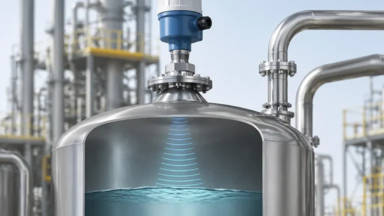
A free space radar level transmitter utilizes electromagnetic waves—specifically microwaves—to determine the distance to a liquid or solid surface. The device emits a signal through an antenna, which travels through the "free space" of the tank headspace, reflects off the material surface, and returns to the sensor.
Time of Flight (ToF)
The fundamental calculation is based on the speed of light ($c \approx 300,000$ km/s). The distance ($D$) is calculated using the formula:
$$D = \frac{c \cdot t}{2}$$
Where $t$ is the measured transit time. Because the speed of light is constant and unaffected by air temperature, pressure, or vapor composition, radar provides superior stability compared to ultrasonic sensors.
FMCW vs. Pulse Radar
Modern industrial radar transmitters generally use one of two modulation techniques:
1. Pulse Radar: The transmitter sends a series of short microwave pulses and measures the time delay of the return echo. While energy-efficient, it often requires sophisticated signal processing to filter out noise.
2. Frequency Modulated Continuous Wave (FMCW): The transmitter emits a continuous signal with a constantly changing frequency (a linear sweep). The reflected signal is compared to the emitted signal. The frequency difference between the two is directly proportional to the distance. FMCW is the preferred technology for high-precision applications due to its superior signal-to-noise ratio.
2. Frequency Selection: 26GHz vs. 80GHz
The operating frequency of a free space radar level transmitter significantly impacts its performance, beam angle, and suitability for specific environments.
* 26GHz (K-Band): This is the traditional industrial standard. It offers a balance between signal strength and antenna size. It is highly effective for large tanks and media with moderate turbulence. However, the beam angle is relatively wide (typically 8° to 20°), which may lead to interference from internal tank structures like agitators or heating coils.
* 80GHz (W-Band): This higher frequency allows for a much narrower beam angle (often as low as 3°). The smaller wavelength provides better reflection from low-dielectric materials and allows the sensor to "see" through narrow nozzles or between internal obstructions. 80GHz transmitters are increasingly used for high-precision liquid measurement and for solids with steep angles of repose.
3. Selection Criteria and Technical Specifications
Choosing the right radar meter requires an assessment of the process media and the vessel geometry. The following table provides a general selection framework for industrial applications.
Selection Reference Table
| Parameter | Liquid (Storage) | Liquid (Process/Agitated) | Solids/Powders | Corrosive Media |
| :— | :— | :— | :— | :— |
| Recommended Frequency | 26GHz or 80GHz | 80GHz | 26GHz or 80GHz | 26GHz (with PTFE) |
| Antenna Type | Horn or Drop | Horn or Lens | Parabolic or Lens | Encapsulated Horn |
| Typical Accuracy | ±2 mm | ±3 mm to ±5 mm | ±10 mm | ±3 mm |
| Measuring Range | Up to 30m | Up to 20m | Up to 70m+ | Up to 20m |
| Dielectric Constant ($ε_r$) | > 1.4 | > 1.9 | > 2.0 | > 1.4 |
| Pressure Limit | Up to 40 Bar | Up to 100 Bar | Atmospheric | Up to 16 Bar |
Antenna Types
* Horn Antenna: The most common design, suitable for most liquid applications. It can be made of stainless steel or coated with PTFE for chemical resistance.
* Drop Antenna: Specifically designed for environments with heavy condensation or buildup. The shape allows droplets to run off the sensing face.
* Parabolic Antenna: Used for long-range measurements (up to 100 meters) and solids, where a large surface area is required to capture weak signals.
* Lens/Encapsulated Antenna: Ideal for corrosive environments as the sensitive electronics are protected behind a flat or curved plastic (PTFE/PP) face.
4. Installation Considerations
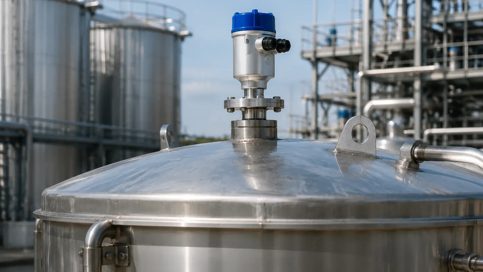
The performance of a free space radar level transmitter is heavily dependent on correct mounting. Even the most advanced signal processing cannot compensate for a poorly positioned sensor.
Beam Angle and Obstructions
The radar signal spreads in a cone shape. Any metal object (ladders, pipes, agitator blades) within this cone will create a "false echo."
* The 1/6 Diameter Rule: For vertical cylindrical tanks, the transmitter should ideally be installed at 1/6 of the tank diameter from the wall. This avoids wall interference while staying clear of the central vortex in agitated tanks.
* Nozzle Height: The antenna should extend slightly beyond the bottom of the mounting nozzle to prevent the nozzle itself from creating signal interference. If the nozzle is very long, a higher frequency (80GHz) or a nozzle extension is required.
Orientation
* Polarization: Radar waves are polarized. Rotating the sensor in its mount can sometimes help minimize reflections from nearby obstructions.
* Verticality: The sensor must be mounted perfectly vertical (perpendicular to the liquid surface). A tilt of even 2-3 degrees can significantly reduce the returned signal strength, especially on calm liquid surfaces.
Avoidance Zones
* The Filling Stream: Never install the radar directly over the inlet pipe. The falling material will scatter the signal and cause erratic readings.
* The Center of the Tank: In many tanks, the center is a focal point for multiple reflections and is also where the vortex forms during agitation. Avoid center mounting unless specifically instructed by the manufacturer.
5. Application Risks and Limitations
While highly versatile, free space radar is not a "one-size-fits-all" solution. Engineers must account for the following physical limitations:
Dielectric Constant ($ε_r$)
The ability of a material to reflect radar waves depends on its dielectric constant. Water has a high $ε_r$ (~80) and is an excellent reflector. Hydrocarbons (oils, solvents) have low $ε_r$ (1.8 to 2.5). If the $ε_r$ is below 1.4, the signal may pass through the material and reflect off the tank bottom, leading to false "tank empty" readings.
Foam and Turbulence
* Foam: Light, airy foam can be transparent to radar, while dense, thick foam can absorb the signal entirely (attenuation). If heavy foam is present, a guided wave radar or a lower frequency free space radar may be more effective.
* Turbulence: Heavy surface agitation scatters the signal. Using a transmitter with advanced software filtering (Echo Tracking) or installing a stilling well can mitigate this.
Dust and Vapor
High-frequency radar (80GHz) performs well in dusty environments (like grain silos) because the narrow beam penetrates dust clouds more effectively. However, extremely high concentrations of steam or certain chemical vapors can attenuate the signal, requiring a lower frequency or specialized antenna purging.
6. Information for International Buyers
When sourcing a free space radar level transmitter from a global manufacturer like Welk, providing comprehensive process data ensures the device is pre-configured for success. International buyers should confirm the following:
1. Media Characteristics: Name of the chemical, dielectric constant, and whether it is prone to crystallization or foaming.
2. Process Conditions: Normal and maximum operating temperature (°C) and pressure (Bar or MPa).
3. Tank Geometry: Total height, nozzle diameter, nozzle height, and a list of internal obstructions.
4. Output Requirements: Standard 4-20mA HART is the industrial default, but RS485 Modbus or Profibus may be required for integration into specific PLC/DCS architectures.
5. Certifications: Determine if the installation area is hazardous (Ex-rated). Common standards include ATEX (Europe), IECEx (Global), and UL/FM (North America).
7. Frequently Asked Questions (FAQ)
Q: Can free space radar measure through a plastic tank roof?
A: Yes. Because plastic is non-conductive, radar signals can penetrate plastic or fiberglass (GRP) tank tops. This allows for "non-invasive" measurement where the sensor is mounted outside the tank, provided the material is not carbon-filled or metallic-coated.
Q: How does radar compare to ultrasonic level sensors?
A: Ultrasonic sensors use sound waves, which require a medium (air) and are affected by temperature, wind, and vacuum. Radar uses electromagnetic waves, which work in a vacuum and are unaffected by air temperature fluctuations, making radar more accurate for outdoor or high-temperature tanks.
Q: Is maintenance required for these sensors?
A: Free space radar is generally low-maintenance because it has no moving parts and does not touch the media. However, in applications with heavy vapor or splashing, the antenna should be checked periodically for buildup. Many modern units include "self-diagnostic" features to alert operators if the signal strength is degrading.
Q: What is the "Dead Zone" or Blocking Distance?
A: This is the area immediately below the antenna where the sensor cannot accurately measure. It typically ranges from 50mm to 300mm depending on the frequency and antenna design. Engineers must ensure the maximum fill level of the tank does not enter this zone.
Conclusion
The free space radar level transmitter represents the pinnacle of non-contact level measurement technology. By understanding the nuances of frequency selection, antenna design, and the physical properties of the process media, engineers can implement a reliable system that minimizes downtime and maximizes data accuracy. For complex applications involving extreme pressures or low-dielectric fluids, consulting with a specialized manufacturer is recommended to ensure the selected Radar Level Meters meet the specific demands of the industrial environment.