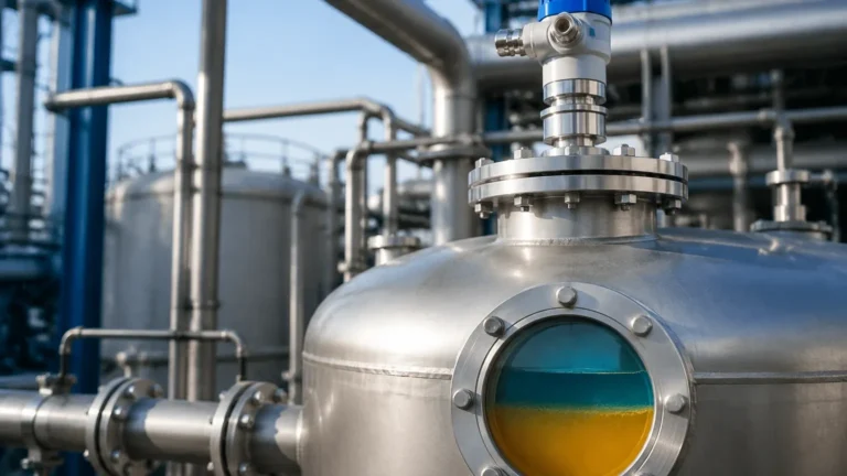
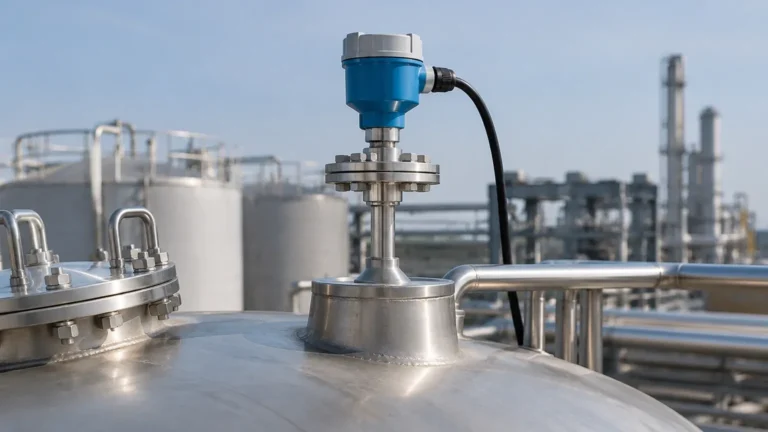
Foxboro Radar Level Transmitter
Foxboro Radar Level Transmitter: An Engineering Guide to Selection and Application
In the landscape of industrial process automation, accurate level measurement is critical for operational safety, inventory management, and process efficiency. Among the various technologies available, radar-based measurement has emerged as a gold standard due to its non-contact nature and resilience in harsh environments. The foxboro radar level transmitter represents a significant segment of this market, offering robust solutions for liquids, pastes, and solids. This guide provides a technical overview of radar technology, specific considerations for Foxboro instrumentation, and practical engineering advice for selecting and installing Radar Level Meters.
Understanding Radar Level Measurement Principles
Before selecting a specific instrument like a foxboro radar level transmitter, it is essential to understand the two primary methods of radar level measurement: Time of Flight (ToF) and Frequency Modulated Continuous Wave (FMCW).
1. Time of Flight (ToF) / Pulse Radar
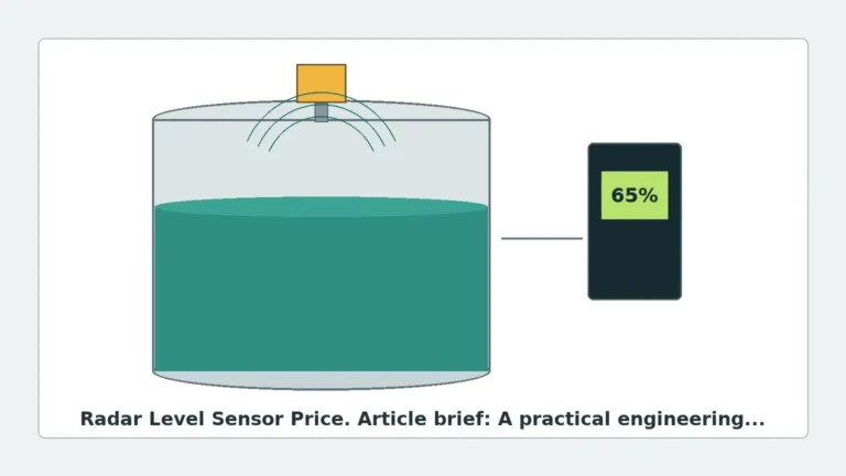
Pulse radar emits short microwave pulses toward the medium's surface. These pulses are reflected back to the sensor. The transmitter measures the time interval between emission and reception. Since the speed of light is constant, the distance is calculated as:
\[ Distance = \frac{c \times t}{2} \]
Where *c* is the speed of light and *t* is the measured time. This method is energy-efficient and suitable for many standard liquid applications.
2. Frequency Modulated Continuous Wave (FMCW)
FMCW radar emits a continuous signal with a constantly changing frequency. When the reflected signal is received, it is compared to the frequency being emitted at that exact moment. The frequency difference is directly proportional to the distance. FMCW is generally more accurate than pulse radar and is preferred for low-dielectric materials or environments with significant surface turbulence.
3. Guided Wave Radar (GWR) vs. Free Space Radar
* Free Space Radar: Emits signals through the air via an antenna (horn, rod, or drop). It is entirely non-contact, making it ideal for corrosive or hygienic applications.
* Guided Wave Radar (GWR): Uses a physical probe (cable or rod) to guide the microwave signal to the liquid surface. This method is highly effective for low-dielectric liquids and applications with heavy foam or steam.
Technical Features of Foxboro Radar Level Transmitters
Foxboro, a brand under the Schneider Electric umbrella, offers the LevelWave series, which includes both free-space and guided-wave models. These instruments are designed to handle the rigors of the oil and gas, chemical, and power industries.
Key Engineering Specifications
* Measurement Range: Typically up to 80 meters (approx. 262 feet) for free-space units.
* Temperature and Pressure: Capable of operating in process temperatures ranging from -60°C to +250°C and pressures up to 40 bar (4.0 MPa), depending on the flange and seal configuration.
* Accuracy: High-precision models offer accuracy within ±2 mm (0.08 inches).
* Communication Protocols: Support for 4-20 mA HART, Foundation Fieldbus, and PROFIBUS PA, ensuring integration with modern Distributed Control Systems (DCS).
Selection Criteria for Industrial Applications
Choosing between different Radar Level Meters requires an analysis of the physical and chemical properties of the media, as well as the vessel geometry.
Material Dielectric Constant (εr)
The dielectric constant is the most critical factor in radar reflection. Materials with a high εr (e.g., water, εr ≈ 80) reflect signals strongly. Materials with a low εr (e.g., hydrocarbons, εr < 2.0) allow most of the signal to pass through, requiring more sensitive electronics or guided wave technology.
Selection Table: Technology vs. Application
| Application Requirement | Free Space Radar (Non-contact) | Guided Wave Radar (GWR) |
| :— | :— | :— |
| Corrosive Liquids | Excellent (with PTFE shielding) | Good (requires compatible probe material) |
| Heavy Foam | Poor to Moderate | Excellent (signal follows probe) |
| Internal Obstructions | Requires careful positioning | Excellent (avoids interference) |
| Low Dielectric (εr < 1.5) | Challenging | Preferred |
| High Turbulence | Moderate | Excellent |
| Hygienic/Sanitary | Excellent | Moderate (probe cleaning required) |
Installation Considerations and Constraints
Proper installation of a foxboro radar level transmitter is vital to prevent signal interference and ensure long-term reliability.
1. Nozzle Geometry
The nozzle height should be kept to a minimum to prevent internal reflections (ringing). If a long nozzle is unavoidable, the antenna should ideally extend below the bottom of the nozzle. For free-space radar, the nozzle diameter must be large enough to accommodate the beam angle of the antenna.
2. The "Dead Zone" (Blocking Distance)
Every radar transmitter has a minimum measurable distance, often called the dead zone or blocking distance. This typically ranges from 50 mm to 500 mm from the flange face. If the liquid level enters this zone, the transmitter may report an error or a fixed maximum value.
3. Beam Path Obstructions
For free-space radar, the microwave beam spreads as it travels. Engineers must ensure the beam path is clear of agitators, heating coils, or ladders. If obstructions are present, "False Echo Suppression" software within the transmitter can be used to map out these static reflections.
4. Orientation and Polarization
Radar signals are polarized. Rotating the transmitter housing can sometimes help minimize reflections from tank walls or internal structures. Most Foxboro units allow for 360-degree housing rotation to facilitate both cable entry and signal optimization.

Limitations and Application Risks
While highly versatile, radar technology is not a universal solution. Engineers should be aware of the following limitations:
* Vacuum Effects: While radar works in a vacuum, the seals and flanges must be rated for the specific pressure conditions. High vacuum can also cause certain liquids to boil, creating heavy vapor that might attenuate the signal.
* Condensation and Buildup: In free-space radar, heavy condensation on the antenna can cause signal loss. Using a PTFE "drop" antenna or a purging system can mitigate this.
* Solid Media Angle of Repose: When measuring solids (powders, grains), the material often forms a cone. The radar signal may reflect away from the sensor at an angle, leading to signal loss. High-frequency (80 GHz) radars are typically better for solids due to their narrower beam.
Maintenance and Troubleshooting
Modern Radar Level Meters are largely maintenance-free because they have no moving parts. However, periodic checks are recommended:
1. Signal Strength Monitoring: Check the signal-to-noise ratio via the HART communicator. A declining signal strength may indicate buildup on the antenna or probe.
2. Seal Integrity: Inspect the process seal (O-rings or gaskets) for signs of chemical degradation, especially in corrosive environments.
3. Firmware Updates: Ensure the transmitter software is updated to the latest version to benefit from improved echo processing algorithms.
Frequently Asked Questions (FAQ)
Q: Can a foxboro radar level transmitter measure interface between two liquids?
A: Yes, Guided Wave Radar (GWR) is particularly effective for interface measurement (e.g., oil over water), provided the upper liquid has a lower dielectric constant than the lower liquid and the layer is thick enough for the transmitter to distinguish the two reflections.
Q: How does 80 GHz radar differ from the 24 GHz models often found in older Foxboro installations?
A: 80 GHz radar offers a much narrower beam angle and a smaller antenna size. This allows it to be installed in smaller nozzles and makes it less likely to hit internal tank obstructions.
Q: Is radar affected by changes in gas composition above the liquid?
A: Unlike ultrasonic sensors, which depend on the speed of sound (which varies with gas density), radar uses electromagnetic waves. These are largely unaffected by changes in pressure, temperature, or the type of gas in the vapor space.
Q: What is the impact of heavy steam on radar accuracy?
A: While radar is much better than ultrasonic in steam, extremely high-pressure steam (as found in boiler drums) can slightly slow down the microwave signal, leading to a small measurement error. High-end transmitters often include compensation factors for these specific conditions.
Conclusion
The foxboro radar level transmitter is a sophisticated instrument capable of providing precise data in the most demanding industrial environments. By understanding the underlying physics of radar waves—specifically how they interact with different dielectric constants and vessel geometries—engineers can select the most appropriate Radar Level Meters for their specific needs. Whether utilizing the non-contact advantages of free-space radar or the stability of guided wave technology, proper selection and installation remain the keys to successful process control and safety.