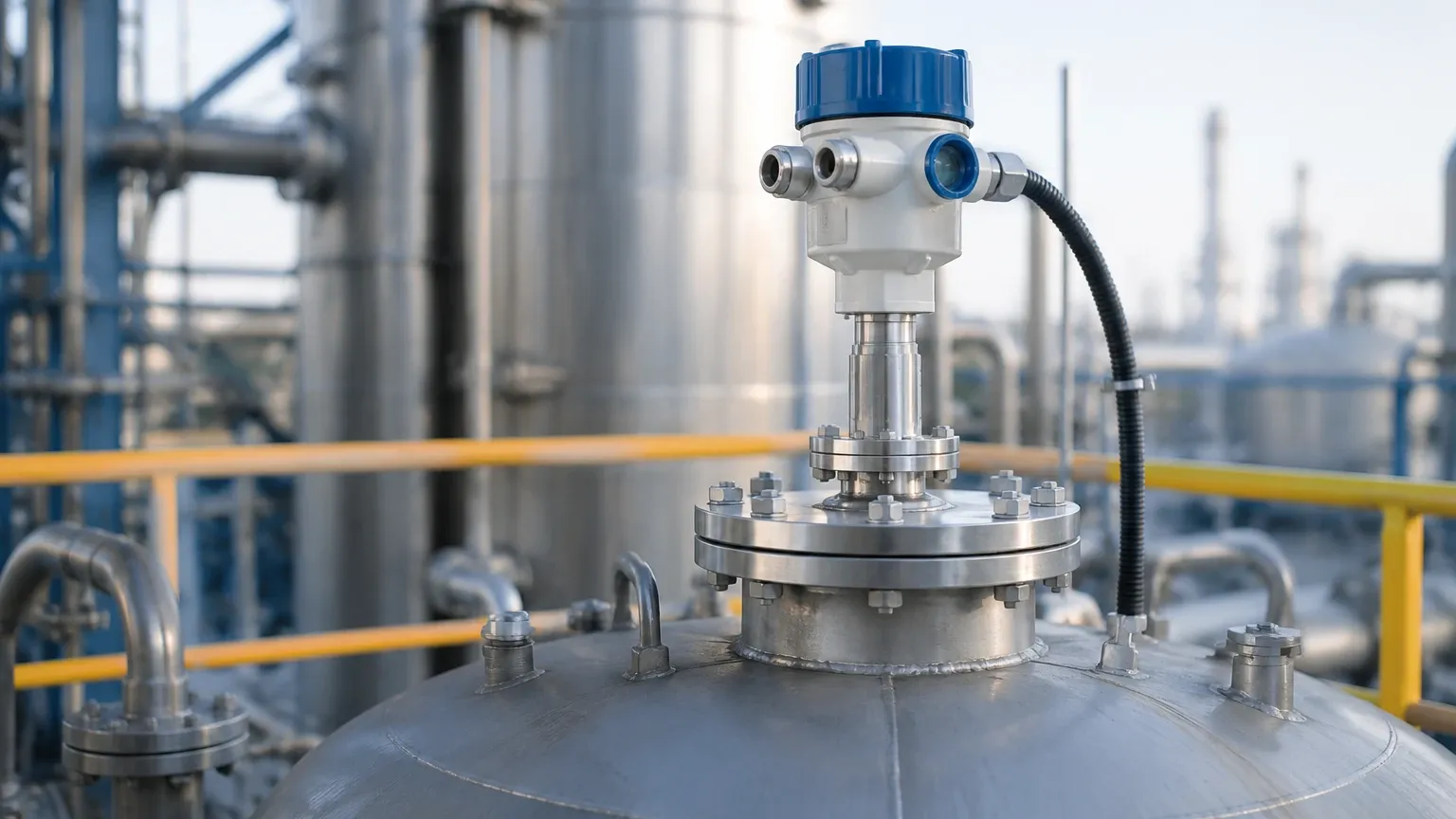
Finetek Radar Level Transmitter
Finetek Radar Level Transmitter: An Engineering Guide to Selection and Application
In the landscape of industrial automation, precise level measurement is a cornerstone of process safety and efficiency. Among the various technologies available, Radar Level Meters have emerged as the gold standard for non-contact measurement in challenging environments. The finetek radar level transmitter, specifically the JFR series, represents a significant segment of this market, offering solutions for both liquid and solid applications. This guide provides a technical deep dive into the principles, selection criteria, and installation requirements for these instruments to assist engineers in making informed procurement decisions.
1. Understanding Radar Measurement Principles
Before selecting a specific finetek radar level transmitter, it is essential to understand the underlying physics that govern radar technology. Radar instruments operate by emitting electromagnetic pulses or continuous waves toward a target material. The time it takes for the signal to reflect off the surface and return to the sensor is used to calculate the distance.
1.1 Pulse Radar vs. FMCW
Most industrial radar transmitters utilize one of two primary methods:
* Pulse Radar: The device emits a short microwave pulse and measures the "Time of Flight" (ToF). While energy-efficient, it often requires a higher dielectric constant from the medium to ensure a strong return signal.
* FMCW (Frequency Modulated Continuous Wave): This technology, often found in high-end Radar Level Meters, emits a continuous signal with a constantly changing frequency. The distance is calculated based on the frequency difference between the emitted and received signals. FMCW offers superior accuracy and a better signal-to-noise ratio, making it ideal for low-dielectric liquids or turbulent surfaces.
1.2 Frequency Bands: 26GHz vs. 80GHz
The frequency of the radar signal dictates the beam angle and the instrument's ability to handle obstructions.
* 26GHz (K-Band): A versatile frequency suitable for most liquid tanks. It handles moderate steam and condensation well but has a wider beam angle, which may interfere with internal tank structures.
* 80GHz (W-Band): The modern standard for precision. With a much narrower beam angle and smaller dead zones, 80GHz transmitters are preferred for tall, narrow silos or tanks with complex internal agitators and pipes.
2. The Finetek Radar Level Transmitter Series
Finetek categorizes its radar offerings primarily under the JFR series. These instruments are designed to meet diverse industrial needs, from basic water storage to high-temperature chemical processing.
2.1 JFR3 FMCW Radar (26GHz)
The JFR3 series utilizes 26GHz FMCW technology. It is typically used for liquid level measurement where high precision (±2mm to ±5mm) is required. It is available with various antenna types, including horn antennas for standard applications and PTFE-sealed antennas for corrosive environments.
2.2 JFR4 80GHz Radar
The JFR4 represents the high-frequency tier. Its 80GHz signal allows for a beam angle as narrow as 3 degrees. This is particularly useful in solids measurement (like grain or cement silos) where the material surface is uneven, or in small process vessels where space is at a premium.
3. Engineering Selection Criteria
Selecting the correct finetek radar level transmitter requires a detailed analysis of the process environment. The following table summarizes the key factors engineers must evaluate:
| Parameter | Consideration | Impact on Selection |
| :— | :— | :— |
| Medium State | Liquid, Slurry, or Granular Solid | Solids require high-frequency (80GHz) and dust-resistant lenses. |
| Dielectric Constant ($ε_r$) | Ability of the material to reflect radar waves | Materials with $ε_r < 1.9$ may require Guided Wave Radar or FMCW with high sensitivity. |
| Process Temperature | Standard (-40°C to 80°C) vs. High Temp | High-temp versions with cooling fins or specialized seals are necessary above 150°C. |
| Process Pressure | Atmospheric vs. High Pressure | Flange ratings (PN16, PN40, etc.) must match vessel design. |
| Measurement Range | Total height of the vessel | Ensure the transmitter's maximum range (e.g., 30m, 70m) exceeds the vessel height. |
| Tank Geometry | Presence of agitators, ladders, or baffles | Narrower beam angles (80GHz) help avoid false echoes from obstructions. |
4. Installation Guidelines and Constraints
Even the most advanced Radar Level Meters will fail if installed incorrectly. For a finetek radar level transmitter, adherence to geometric constraints is mandatory.
4.1 Nozzle Height and Diameter
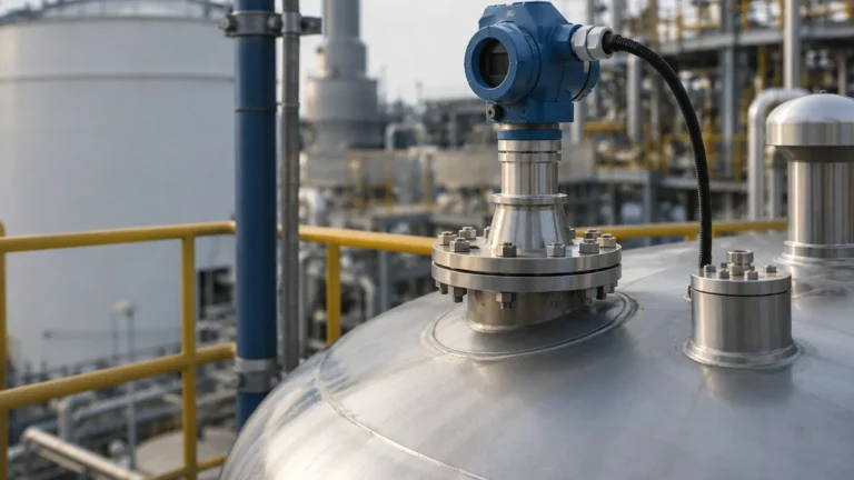
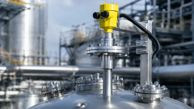
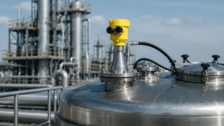
The nozzle (the mounting pipe on top of the tank) should be as short as possible. If the nozzle is too long or narrow, the radar signal may reflect off the nozzle walls, creating a "ringing" effect that obscures the true level signal. Ideally, the antenna should extend slightly past the bottom of the nozzle.
4.2 Distance from Tank Wall
To avoid interference from wall reflections (multipath interference), the transmitter should be installed at a distance from the wall equal to at least 1/6th of the tank diameter. It should never be mounted in the exact center of a domed-roof tank, as this can concentrate parasitic reflections.
4.3 Obstruction Avoidance
Internal structures such as heating coils, ladders, and agitator blades are common sources of false echoes. When using a finetek radar level transmitter, engineers should utilize the "False Echo Suppression" or "Background Subtraction" software features during commissioning to map out these static reflections.
4.4 Dead Zones (Blind Spots)
Every radar sensor has a near-field blind spot, typically ranging from 50mm to 300mm from the reference point of the antenna. Measurement is not possible within this zone. Ensure the maximum expected fill level does not enter this dead zone to prevent signal loss.
5. Limitations and Application Risks
While radar is highly reliable, certain conditions can attenuate the signal or cause measurement errors:
1. Heavy Foam: Dense, thick foam (like protein foam) can absorb the radar signal entirely, preventing a return echo. In such cases, a displacement-type level meter or a magnetic level gauge may be more appropriate.
2. Extremely Low Dielectric Materials: Liquid hydrocarbons (like hexane) have very low reflectivity. If the surface is also turbulent, the radar may lose the signal. High-sensitivity FMCW units are required here.
3. Heavy Dust and Build-up: In solids applications, heavy dust can coat the antenna. While 80GHz radar penetrates dust clouds well, physical build-up on the lens can degrade performance. Air purging systems are often recommended for these scenarios.
4. Vacuum Conditions: While radar works in a vacuum (as electromagnetic waves do not require a medium), the mechanical seals of the transmitter must be rated for vacuum service to prevent internal damage.
6. Technical Maintenance and Troubleshooting
Modern radar transmitters are virtually maintenance-free due to the lack of moving parts. However, periodic checks are recommended:
* Signal Strength Monitoring: Check the echo curve via the local display or HART communicator. A declining signal-to-noise ratio may indicate antenna fouling.
* Seal Integrity: Inspect the process connection for leaks, especially in pressurized or corrosive applications.
* Firmware Updates: Ensure the signal processing algorithms are up to date to benefit from improved false-echo filtering.
7. Frequently Asked Questions (FAQ)
Q: Can a finetek radar level transmitter measure through a plastic tank lid?
A: Yes. Since plastic (like PE or PP) is transparent to microwaves, radar can measure the level from outside the tank. However, this results in some signal attenuation, and the lid must be non-conductive.
Q: What is the difference between 4-20mA and RS485 output for these devices?
A: 4-20mA (often with HART) is the industrial standard for point-to-point analog communication. RS485 (Modbus) allows for digital bus networking, enabling multiple transmitters to be connected to a single PLC port over long distances.
Q: How does the dielectric constant affect the accuracy?
A: The dielectric constant does not affect the *speed* of the radar wave (and thus the distance calculation), but it affects the *strength* of the reflection. Higher $ε_r$ values provide a stronger, more reliable signal.
Q: Is it necessary to empty the tank to calibrate the radar?
A: No. One of the primary advantages of radar technology is that it can be calibrated using the vessel dimensions and a single reference point measurement, without needing to cycle the fluid level.
Conclusion
The finetek radar level transmitter is a robust tool for modern industrial processes, provided that the selection process accounts for the specific dielectric and geometric properties of the application. By prioritizing high-frequency FMCW technology for complex environments and adhering to strict installation clearances, facilities can achieve maintenance-free, high-precision level monitoring. For further technical specifications and model comparisons, engineers should consult detailed product documentation to match the instrument to their specific hazardous area or sanitary requirements.