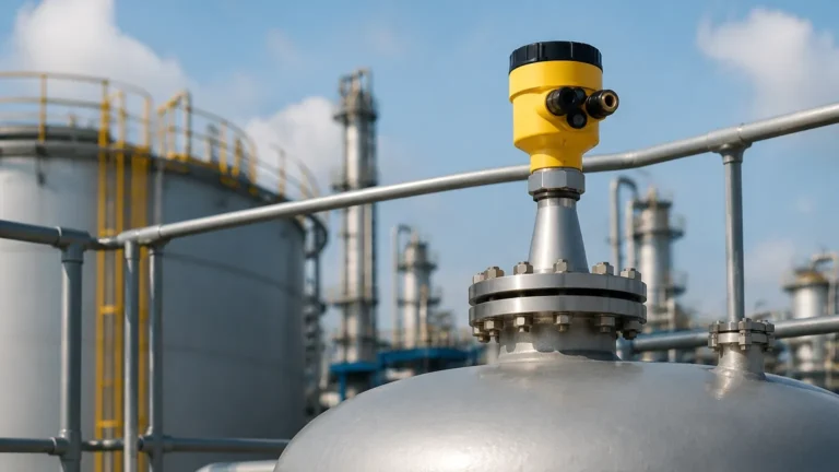
Working Principle of Guided Wave Radar Level Transmitter
Working Principle of Guided Wave Radar Level Transmitter: A Technical Engineering Guide
In the landscape of industrial process automation, achieving precise level measurement is critical for operational safety, inventory management, and process efficiency. Among the various technologies available, Radar Level Meters have emerged as the gold standard for challenging environments. Specifically, the guided wave radar (GWR) transmitter offers a robust solution for applications where traditional non-contact methods might fail. This guide explores the working principle of guided wave radar level transmitter technology, its mechanical configurations, and the engineering considerations necessary for successful deployment.
Understanding the Fundamental Measurement Principle
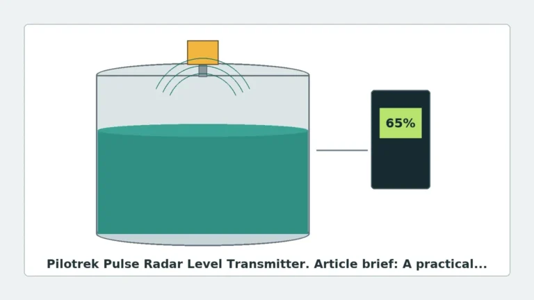
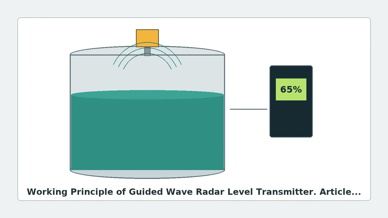
To specify the correct instrument, an engineer must first understand the physics governing the device. The working principle of guided wave radar level transmitter technology is based on Time Domain Reflectometry (TDR). While non-contact radar sends electromagnetic pulses through the air, GWR utilizes a physical probe—a waveguide—to direct these pulses from the transmitter head to the process medium.
The TDR Process
1. Pulse Emission: The transmitter electronics generate low-energy, high-frequency electromagnetic pulses (typically in the gigahertz range).
2. Guided Propagation: These pulses travel along the probe (the waveguide) at the speed of light.
3. Reflection (The Echo): When the pulse reaches the surface of the medium being measured, a portion of the pulse energy is reflected back toward the transmitter. This reflection occurs due to a change in the dielectric constant ($ε_r$) between the upper medium (usually air or gas) and the process medium (liquid or solid).
4. Time-of-Flight Calculation: The device measures the time interval between the pulse emission and the reception of the reflected signal. Since the speed of the pulse is constant, the distance ($D$) to the surface is calculated using the formula:
$D = (c imes t) / 2$
where $c$ is the speed of light and $t$ is the measured time.
5. Level Conversion: The transmitter subtracts the measured distance from the total tank height (the zero point) to determine the actual level of the material.
Unlike ultrasonic sensors, which rely on sound waves and are affected by air temperature and pressure, the electromagnetic pulses in GWR are virtually unaffected by changes in the vapor space, such as dust, steam, or fluctuating pressure.
Probe Geometries and Selection Criteria
The effectiveness of Radar Level Meters depends heavily on the probe design. The probe acts as the interface between the electronics and the process. Choosing the right geometry is essential for signal integrity.
1. Single Rod or Cable Probes
Single-element probes are the most versatile and easiest to clean. They are ideal for liquids with high dielectric constants (water-based) and are less prone to material build-up. However, they have a weaker electromagnetic field concentration, making them less suitable for low-dielectric hydrocarbons unless installed in a bypass pipe or stilling well.
2. Twin Rod or Cable Probes
Twin probes consist of two parallel elements. The electromagnetic field is concentrated between the two rods, providing a stronger reflection signal than a single rod. These are often used for liquids with lower dielectric constants or in applications where the tank walls are too far away to provide a reference.
3. Coaxial Probes
Coaxial probes consist of a central rod inside an outer perforated tube. This design offers the highest signal-to-noise ratio because the electromagnetic field is entirely contained within the tube. Coaxial probes are the preferred choice for low-dielectric liquids ($ε_r < 1.6$) and applications with high turbulence or foam. The drawback is their susceptibility to clogging if the medium contains solids or is highly viscous.
Selection Table: Probe Type vs. Application
| Probe Type | Best For | Dielectric Range (ε_r) | Viscosity Limit | Resistance to Build-up |
| :— | :— | :— | :— | :— |
| Single Rod | Water-based liquids, large tanks | > 1.9 (with stilling well > 1.4) | High | Excellent |
| Twin Rod | Low-dielectric liquids, oils | > 1.9 | Medium | Fair |
| Coaxial | Propane, butane, high turbulence | > 1.4 | Low | Poor |
The Role of the Dielectric Constant (ε_r)
The dielectric constant is the most critical factor in the working principle of guided wave radar level transmitter performance. It determines the strength of the reflection.
* High Dielectric (ε_r > 10): Water-based media reflect almost all the pulse energy, resulting in a very strong, reliable signal.
* Low Dielectric (ε_r 1.4 to 4): Hydrocarbons and solvents reflect only a small portion of the energy. In these cases, a coaxial probe or a stilling well is required to concentrate the signal and prevent it from being lost in the background noise.
If the dielectric constant is extremely low, the pulse may pass through the liquid entirely and reflect off the bottom of the tank. Advanced GWR transmitters can use "End-of-Probe" (EOP) shift logic to calculate the level based on the slowed speed of the pulse as it travels through the liquid, though this is a specialized configuration.
Installation Considerations and Constraints
Proper installation is paramount to ensure the accuracy of Radar Level Meters. Even the most advanced GWR can provide false readings if physical constraints are ignored.
1. The Dead Zone (Blocking Distance)
Every GWR transmitter has an upper and lower "dead zone" (typically 50 mm to 300 mm / 2 to 12 inches). In the upper dead zone, near the mounting flange, the signal is too close to the electronics to be measured accurately. Engineers must ensure the maximum fill level does not enter this zone, or use a nozzle extension to lift the transmitter head.
2. Nozzle Dimensions
The mounting nozzle should be as short and wide as possible. If the nozzle is too narrow or too long, it can create parasitic reflections that interfere with the initial pulse. For single rod probes, the nozzle diameter should ideally be at least 50 mm (2 inches).
3. Clearance from Internal Obstructions
While the probe guides the signal, the electromagnetic field still extends slightly beyond the probe surface (especially with single rod designs). The probe should be installed at least 300 mm (12 inches) away from tank walls, agitators, or ladders to prevent interference.
4. Probe Anchoring
In tall tanks or vessels with high agitation, cable probes must be anchored to the bottom to prevent them from swinging and hitting the tank walls or internal structures. If anchoring is used, ensure the anchor is made of non-conductive material or accounted for in the transmitter's software.
GWR vs. Non-Contact Radar: When to Choose Which?
While both are categorized as radar level meters, GWR has distinct advantages in specific process conditions:
* Foam: GWR is generally superior in foamy applications. Because the signal is guided, it can often penetrate through light foam to reach the liquid surface. Non-contact radar pulses are frequently absorbed or scattered by foam.
* Turbulence: In boiling or agitated liquids, GWR provides a more stable reading because the probe acts as a mechanical stabilizer for the signal path.
* Internal Obstructions: If a tank is crowded with pipes and supports, a non-contact radar may struggle with "false echoes." A GWR probe can be positioned to bypass these obstructions entirely.
* Dust and Vapor: GWR is immune to heavy dust (e.g., in grain silos) and thick steam, which can attenuate the signal of non-contact radar or ultrasonic sensors.
Limitations and Application Risks
Despite its versatility, GWR is not a universal solution. Engineers should be aware of the following risks:
* Material Build-up: If a conductive medium (like a metallic slurry) bridges the gap between the probe and the tank wall, or coats the probe of a twin/coaxial design, the signal will reflect at the point of the build-up rather than the actual level.
* Mechanical Stress: In high-viscosity liquids or heavy solids, the lateral force (pull-down force) on a cable probe can be immense, potentially damaging the transmitter head or pulling the probe apart.
* Corrosion: Because the probe is in constant contact with the medium, material compatibility is vital. Standard probes are 316L stainless steel, but aggressive chemicals may require Hastelloy or PTFE coating.
Buyer’s Confirmation Checklist
When sourcing a GWR level transmitter from an international manufacturer like Welk, providing the following data ensures the instrument is correctly configured for your site:
1. Medium Properties: What is the dielectric constant? Is it corrosive, viscous, or prone to coating?
2. Process Conditions: What are the maximum and minimum operating temperatures and pressures? (GWR can typically handle up to 400°C / 752°F and 400 bar / 5800 psi in specialized designs).
3. Vessel Geometry: What is the total height? Is there a mounting nozzle? Are there internal obstructions?
4. Connection Type: Flanged (ANSI/DIN) or threaded (NPT/G)?
5. Output Requirements: 4-20mA HART, Modbus, or Foundation Fieldbus?
Frequently Asked Questions (FAQ)
Q: Can guided wave radar measure the interface between two liquids?
A: Yes. One of the primary strengths of the working principle of guided wave radar level transmitter technology is interface measurement. If the top liquid has a lower dielectric constant (e.g., oil) and the bottom liquid has a higher dielectric (e.g., water), the pulse will reflect off both surfaces, allowing the device to report both the total level and the interface level.
Q: Does the probe need to be perfectly vertical?
A: While vertical installation is ideal, GWR can operate at an angle. However, the transmitter must be calibrated for the angle to ensure the time-of-flight distance is correctly converted to vertical height.
Q: How do I handle probe lengths longer than 6 meters?
A: For lengths exceeding 4-6 meters (13-20 feet), cable probes are used instead of rigid rods. These are shipped coiled and are tensioned on-site with a weight or anchor.
Q: Is GWR affected by vacuum conditions?
A: No. Since electromagnetic waves do not require a medium for propagation, GWR works perfectly in a vacuum, unlike ultrasonic sensors which require air.
Conclusion
The working principle of guided wave radar level transmitter technology offers a highly reliable, low-maintenance solution for complex industrial level challenges. By guiding the electromagnetic pulse directly to the medium, GWR bypasses many of the environmental factors that plague other sensors. Whether dealing with low-dielectric fuels, agitated chemical reactors, or interface measurement in separators, understanding the probe selection and installation constraints is the key to engineering success. For those evaluating technical specifications for upcoming projects, reviewing the various configurations of Radar Level Meters will provide the necessary foundation for a robust instrumentation strategy.
Download Working Principle of Guided Wave Radar Level Transmitter as a PDF