Guided Wave Radar Level Transmitter Non Contact
Guided Wave Radar Level Transmitter Non Contact: A Technical Engineering Guide
In modern industrial process control, selecting the correct level measurement technology is critical for operational safety, efficiency, and inventory accuracy. Among the most reliable technologies available today are Radar Level Meters, which utilize electromagnetic waves to determine the distance to a product surface.
When researching these solutions, engineers often encounter the term "guided wave radar level transmitter non contact." From a technical standpoint, this phrase encompasses two distinct branches of radar technology: Guided Wave Radar (GWR), which is a contact-based measurement using a physical probe, and Non-Contact Radar (NCR), which transmits waves through the air. This guide explores the measurement principles, selection criteria, and installation requirements for both technologies to help industrial buyers make informed decisions.
1. Understanding Radar Measurement Principles
Before selecting an instrument, it is essential to understand how electromagnetic energy interacts with the process media. Both technologies rely on the speed of light and the dielectric constant ($ε_r$) of the material being measured.
Guided Wave Radar (GWR)
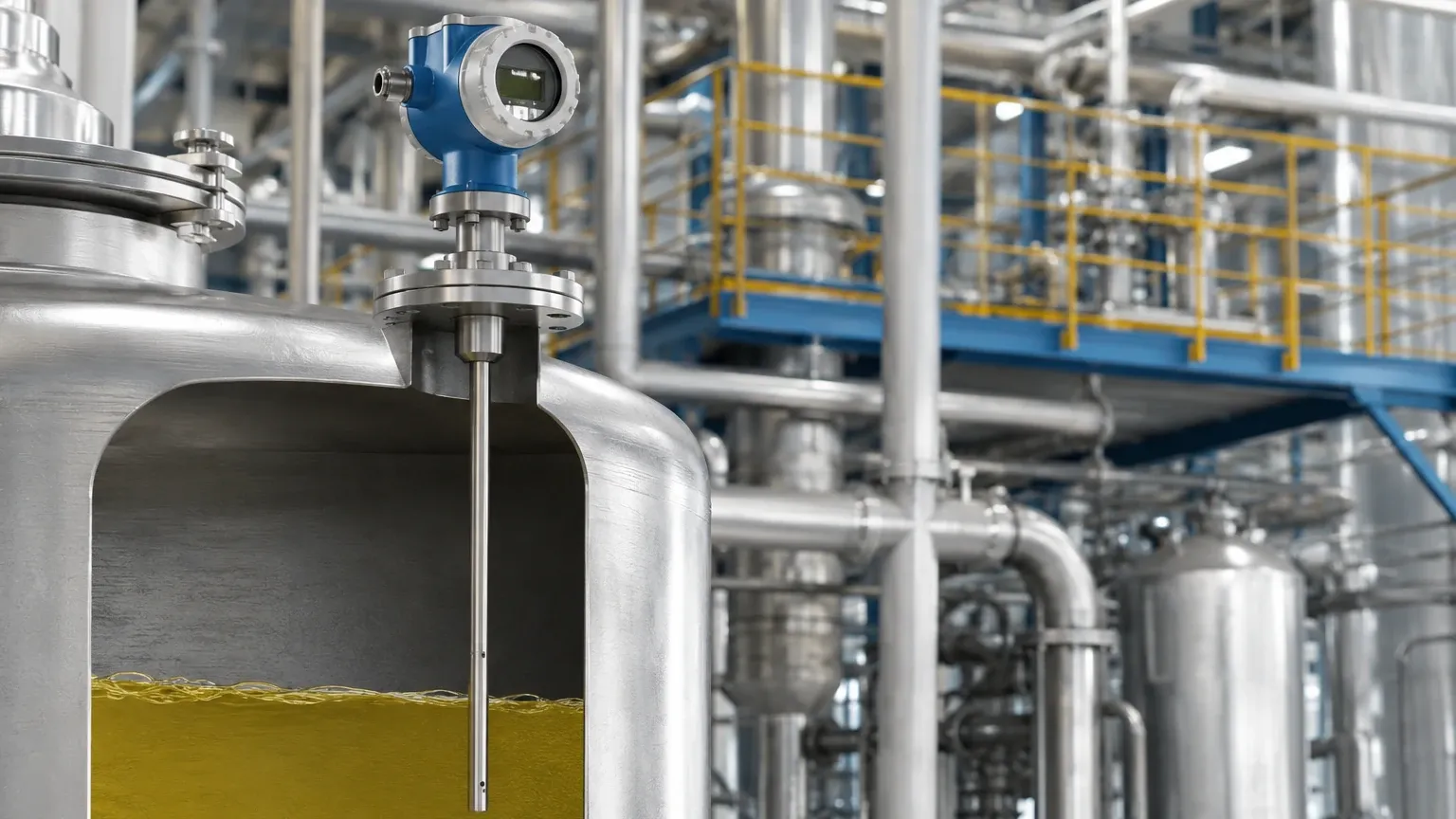
Guided Wave Radar operates on the principle of Time Domain Reflectometry (TDR). The transmitter generates a low-energy microwave pulse that is guided along a physical probe (a rod, coaxial tube, or flexible cable). When the pulse reaches the surface of the medium, a portion of the energy is reflected back to the transmitter due to the change in the dielectric constant between the air/gas space and the process material.
Because the pulse is confined along a waveguide, the signal is concentrated, making GWR highly efficient for materials with low dielectric constants or in vessels with complex internal geometries.
Non-Contact Radar (NCR)
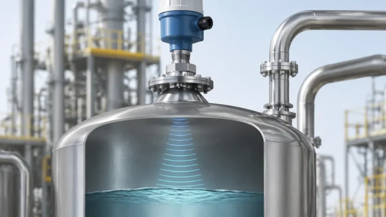
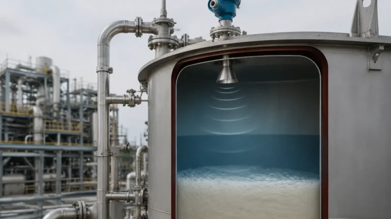
Non-contact radar transmitters emit electromagnetic pulses or a continuous wave (FMCW – Frequency Modulated Continuous Wave) from an antenna. These waves travel through the vapor space, reflect off the surface of the liquid or solid, and return to the antenna. The device calculates the level based on the time-of-flight or the frequency shift of the reflected signal.
Non-contact radar is preferred when the media is highly corrosive, abrasive, or when the process requires a hygienic environment where no physical probe should touch the material.
2. Technical Comparison: Contact vs. Non-Contact
Choosing between a GWR and a non-contact radar depends on the physical characteristics of the tank and the chemical properties of the media. The following table summarizes the key differences:
| Feature | Guided Wave Radar (GWR) | Non-Contact Radar (NCR) |
| :— | :— | :— |
| Measurement Type | Contact (Probe-based) | Non-Contact (Antenna-based) |
| Dielectric Constant (ε_r) | Works with ε_r as low as 1.4 | Generally requires ε_r > 1.9 |
| Surface Turbulence | Excellent resistance; probe stabilizes signal | Can cause signal scattering |
| Foam Presence | Can penetrate light foam | Often reflected by dense foam |
| Internal Obstructions | Ignores obstructions away from the probe | Must account for beam angle/false echoes |
| Vessel Height | Limited by probe length (up to 60m) | Can measure up to 120m+ |
| Maintenance | Probe may require cleaning if sticky | Minimal maintenance (no contact) |
3. Selection Criteria for Industrial Applications
When evaluating a guided wave radar level transmitter non contact solution, engineers must consider the following environmental factors:
Dielectric Constant (ε_r)
The dielectric constant of the medium is the most critical factor in radar signal reflection. Water has a high dielectric (ε_r ≈ 80), providing a strong reflection. Hydrocarbons, oils, and certain powders have low dielectrics (ε_r < 3). GWR is typically superior for low-dielectric fluids because the waveguide prevents signal dissipation.
Vessel Geometry and Internal Obstructions
Non-contact radar emits a beam that spreads as it travels. If a tank contains agitators, heating coils, or ladders, these can create "false echoes." While modern software can map out these echoes, GWR is often simpler in these environments because the measurement is confined to the immediate vicinity of the probe.
Media Physical State
* Corrosive Liquids: Non-contact radar is ideal as it avoids material degradation of the sensor.
* Sticky or Viscous Media: GWR probes can suffer from "bridging" or buildup, which may cause measurement errors. In such cases, non-contact radar or a GWR with a coated probe is recommended.
* Solids and Powders: High-frequency non-contact radar is often preferred for solids to avoid the mechanical pull-down forces that can snap a GWR cable in a silo.
4. Installation Considerations and Best Practices
Proper installation is the difference between a reliable instrument and constant troubleshooting.
For Guided Wave Radar:
1. Blocking Distance: There is a "dead zone" at the top and bottom of the probe where measurement is not possible. Ensure the probe length is calculated based on the full range of the vessel.
2. Probe Proximity: The probe must be kept at a minimum distance (typically 100mm to 300mm) from the tank wall and internal metal structures to prevent signal interference.
3. Nozzle Mounting: If mounting in a nozzle, the nozzle diameter and height must be checked against the manufacturer's specifications to prevent signal loss at the entry point.
For Non-Contact Radar:
1. Beam Angle: The antenna's beam angle determines the "footprint" of the signal. The beam should not intersect with the tank wall or internal obstructions.
2. Nozzle Interference: The antenna should ideally extend slightly past the bottom of the mounting nozzle to ensure a clear transmission path.
3. Orientation: The transmitter should be mounted perpendicular to the product surface. For solids, an aiming flange may be required to compensate for the angle of repose.
5. Limitations and Application Risks
While Radar Level Meters are highly versatile, they are not universal solutions.
* Vacuum Conditions: While radar works well in a vacuum, the sealing (O-rings and glass-to-metal seals) must be rated for the specific pressure and temperature of the process.
* Extremely Dense Steam: In high-pressure boiler applications, the high density of steam can slow down the microwave pulse, leading to a "propagation delay" that results in a measurement error. Special GWR units with dynamic vapor compensation are required for these scenarios.
* Heavy Dust: In silos, extremely heavy dust during filling can attenuate the signal of non-contact radar. Higher frequency (80GHz) radar is better at penetrating dust than lower frequency (6GHz or 26GHz) models.
6. Buyer's Checklist: Information for Manufacturers
To ensure the correct configuration of a guided wave radar level transmitter non contact system, international buyers should provide the following data to the manufacturer:
1. Media Type: Chemical composition and dielectric constant.
2. Process Temperature and Pressure: Minimum, normal, and maximum values.
3. Vessel Dimensions: Total height, diameter, and nozzle specifications.
4. Interface Measurement: Are you measuring a single level or the interface between two liquids (e.g., oil and water)? GWR is the standard for interface measurement.
5. Output Requirements: 4-20mA HART, Modbus RS485, Foundation Fieldbus, or Profibus.
6. Certifications: Is the area hazardous (ATEX/IECEx/SIL2)?
7. Frequently Asked Questions (FAQ)
Q: Can a non-contact radar measure through a plastic tank lid?
A: Yes. Since plastic has a low dielectric constant, microwaves can pass through it. This allows for measurement without opening the tank, provided the plastic is not too thick or reinforced with metal.
Q: Why would I choose GWR over non-contact radar for a low-dielectric liquid?
A: In low-dielectric liquids, the reflection is weak. A non-contact radar signal might dissipate too much, whereas a GWR probe keeps the signal concentrated, ensuring a return pulse strong enough for the electronics to detect.
Q: Is radar affected by changes in air temperature or pressure?
A: Unlike ultrasonic sensors, which rely on the speed of sound (affected by air density), radar uses electromagnetic waves. These are largely unaffected by changes in temperature, pressure, or the presence of vapors, making radar much more accurate in fluctuating process conditions.
Q: What is the maintenance schedule for a radar level meter?
A: Non-contact units are virtually maintenance-free. For GWR, periodic inspection of the probe for coating or physical damage is recommended, especially in corrosive or crystallizing media.
Conclusion
Whether utilizing a contact-based guided wave radar or a non-contact radar transmitter, these instruments provide the precision required for modern industrial automation. By understanding the dielectric properties of the media and the mechanical constraints of the vessel, engineers can deploy Radar Level Meters that offer years of reliable service with minimal intervention. When in doubt, consulting with a technical specialist to perform a signal-to-noise ratio calculation based on your specific application is the best path toward a successful installation.
Download Guided Wave Radar Level Transmitter Non Contact as a PDF