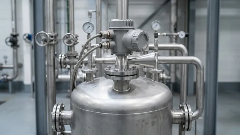
Radar Based Level Transmitter
Radar Based Level Transmitter: A Technical Engineering Guide to Selection and Application
In the landscape of industrial automation, the requirement for precise, non-contact, and reliable liquid and solid level measurement has led to the widespread adoption of the radar based level transmitter. Unlike traditional mechanical or hydrostatic methods, radar technology utilizes electromagnetic waves to determine the distance to a product surface, offering high immunity to changes in process temperature, pressure, and vapor composition.
For engineers and procurement specialists, selecting the appropriate Radar Level Meters requires a deep understanding of microwave physics, vessel geometry, and the dielectric properties of the medium being measured. This guide examines the fundamental principles, technology variants, and practical installation considerations necessary for successful deployment in B2B industrial environments.
1. Measurement Principles of Radar Technology
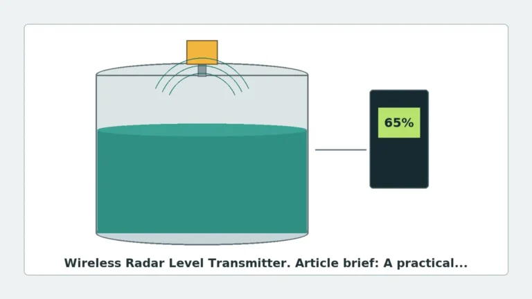
Radar level measurement is based on the "Time of Flight" (ToF) principle. The transmitter, mounted at the top of a vessel, emits electromagnetic pulses or a continuous wave toward the material surface. These waves travel at the speed of light ($c \approx 300,000$ km/s). When the waves encounter a change in the dielectric constant (the boundary between air/vapor and the product), a portion of the energy is reflected back to the sensor.
The distance ($D$) is calculated using the formula:
$$D = \frac{c \times t}{2}$$
Where:
* $c$ is the speed of light.
* $t$ is the measured transit time from emission to reception.
Pulse Radar vs. FMCW Radar
Modern radar based level transmitters generally fall into two categories based on their signal modulation:
* Pulse Radar: This technology emits short microwave pulses and measures the time it takes for the pulse to return. It is known for its energy efficiency and is often used in battery-powered or loop-powered applications. Pulse radar is effective for many standard liquid storage applications but may struggle with very low dielectric materials or high-turbulence environments.
* FMCW (Frequency Modulated Continuous Wave): Instead of pulses, FMCW transmitters emit a continuous signal with a constantly changing frequency (a linear sweep). The difference in frequency between the emitted signal and the reflected signal is proportional to the distance. FMCW provides significantly higher resolution and a better signal-to-noise ratio, making it the preferred choice for high-precision custody transfer and complex industrial processes.
2. Guided Wave Radar (GWR) vs. Non-Contact Radar
When specifying a radar based level transmitter, the first major decision is whether to use a contact (guided) or non-contact system.
Non-Contact Radar
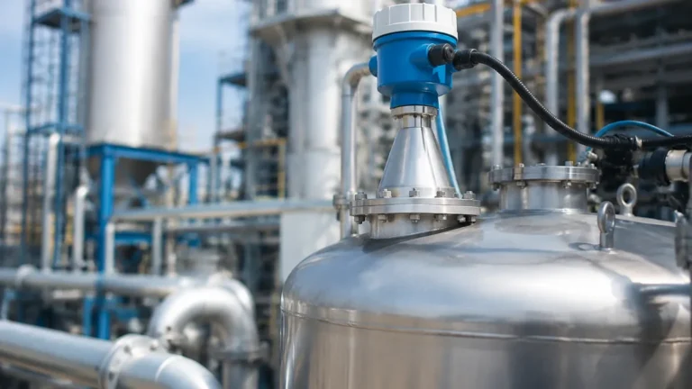
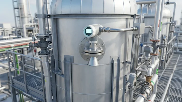
Non-contact radar level meters emit signals through the air via an antenna (horn, drop, or lens type).
* Advantages: No moving parts, no contact with corrosive or abrasive media, and easy to retrofit without emptying the tank.
* Ideal for: Corrosive liquids, hygienic food and beverage applications, and large-scale bulk solids storage.
Guided Wave Radar (GWR)
GWR utilizes a physical probe (cable or rod) to guide the microwave signal directly to the surface.
* Advantages: The signal is concentrated along the probe, reducing energy loss. It is highly effective for low dielectric constants (DK as low as 1.4), heavy foam, and applications with internal obstructions.
* Ideal for: Bypass chambers, small tanks with internal agitators, and interface measurement (e.g., oil over water).
3. The Role of Frequency in Selection
The frequency of the radar signal—typically ranging from 6 GHz to 80 GHz—dictates the beam angle and the instrument's ability to handle specific process conditions.
| Frequency Range | Beam Angle | Typical Applications | Strengths |
| :— | :— | :— | :— |
| 6 GHz – 10 GHz (C-Band) | Wide (approx. 20°–30°) | Heavy steam, foam, and turbulence. | Penetrates vapor and foam better than high frequencies. |
| 26 GHz (K-Band) | Medium (approx. 8°–12°) | Standard chemical tanks, oils, and water treatment. | Good balance of precision and signal strength. |
| 80 GHz (W-Band) | Narrow (approx. 3°–4°) | Tall, narrow silos, tanks with agitators, and high-precision liquids. | Exceptional focusing, ignores internal obstructions, and small dead zones. |
High-frequency 80 GHz Radar Level Meters have become the industry standard for new installations due to their narrow beam, which avoids false echoes from tank walls and internal structures like heating coils or ladders.
4. Understanding the Dielectric Constant ($ε_r$)
The dielectric constant of the medium is the most critical factor in determining signal reflection strength.
* High Dielectric ($ε_r > 10$): Water-based liquids provide strong reflections and are easy to measure.
* Low Dielectric ($ε_r < 3$): Hydrocarbons, solvents, and dry powders reflect very little energy.
In cases where the dielectric constant is extremely low (e.g., liquid nitrogen or certain dry plastics), a GWR probe or a high-sensitivity FMCW transmitter with a large horn antenna is required to capture a usable signal.
5. Installation Guidelines and Constraints
Proper installation is paramount to preventing "false echoes"—reflections from non-target objects that the transmitter might mistake for the product level.
Nozzle Dimensions
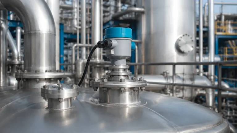
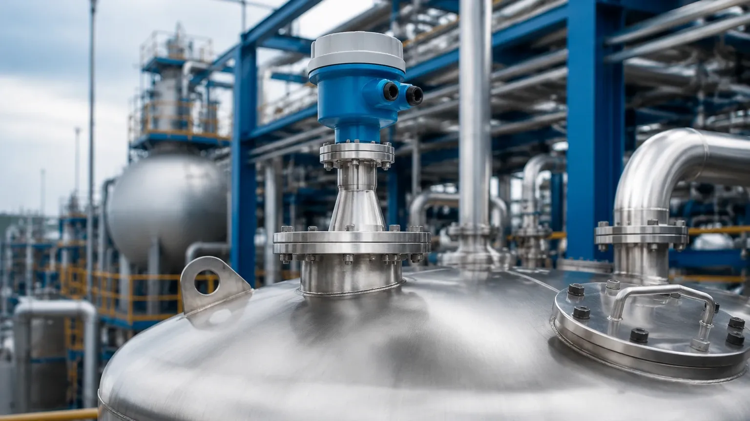
The mounting nozzle should be as short as possible. If the nozzle is too long or narrow, the radar signal will reflect off the nozzle's inner edge before it even enters the tank. For 80 GHz units, nozzle heights up to 500 mm (approx. 20 inches) are often acceptable, but for lower frequencies, the nozzle should ideally be shorter than its diameter.
Positioning and Clearance
* Wall Distance: Never mount the transmitter in the exact center of a dome-roof tank, as this can cause multiple reflections. Conversely, avoid mounting too close to the wall (minimum 200 mm or 8 inches) to prevent interference.
* Obstructions: Ensure the signal path is clear of agitators, spray balls, and ladders. If an obstruction is unavoidable, most modern radar based level transmitters include "False Signal Suppression" software to digitally map out and ignore these static reflections.
* Inflow: Do not install the sensor directly above the product inlet, as the falling stream will cause signal scattering and erratic readings.
Dead Zones (Blocking Distance)
Every radar sensor has a "dead zone" near the antenna (typically 50 mm to 300 mm) where measurement is impossible. Ensure the maximum expected level of the product does not enter this zone to avoid signal loss.
6. Application Selection Matrix
| Application | Recommended Technology | Why? |
| :— | :— | :— |
| Corrosive Chemical Storage | Non-contact 80 GHz (PTFE Lens) | High frequency avoids wall interference; PTFE resists corrosion. |
| Oil/Water Interface | Guided Wave Radar (GWR) | Microwaves pass through the upper layer and reflect off the lower layer. |
| Cement Silos (High Dust) | 80 GHz Non-contact | Narrow beam penetrates dust; high frequency handles low-reflectivity solids. |
| Asphalt/Bitumen (High Temp) | Non-contact with Cooling Fin | Protects electronics from extreme process heat (up to 250°C+). |
| Small Process Vessels | 80 GHz Radar | Small antenna size and narrow beam fit into tight spaces. |
7. Limitations and Risk Mitigation
While highly versatile, radar technology faces specific limitations:
1. Heavy Foam: Dense, thick foam can absorb microwave signals entirely. In these cases, C-Band radar or GWR is preferred over high-frequency units.
2. Vacuum Conditions: While radar works in a vacuum, the flange seals must be rated for the pressure differential.
3. Condensation: Heavy droplets on the antenna can attenuate the signal. Selecting a "drop" or "lens" antenna shape allows condensation to run off rather than pool on the emitting surface.
4. Multi-Chamber Tanks: In tanks with internal baffles, signal paths must be carefully calculated to ensure the radar reaches the lowest possible level.
8. Frequently Asked Questions (FAQ)
Q: Does pressure affect radar level measurement?
A: No. Unlike ultrasonic sensors, which rely on air density to transmit sound, radar uses electromagnetic waves that are unaffected by pressure or vacuum.
Q: Can a radar based level transmitter measure through a plastic tank wall?
A: Yes. If the tank is made of a non-conductive material (like PE, PP, or PVC) and is not reinforced with metal, the radar signal can pass through the wall to measure the level inside. This is common in IBC totes and chemical plastic tanks.
Q: What is the maintenance requirement for a radar level meter?
A: Because non-contact radar has no moving parts, maintenance is minimal. Periodic inspection of the antenna for buildup and verification of the 4-20mA or digital output (HART, Modbus, Profibus) is usually sufficient.
Q: How do I choose between a 2-wire and 4-wire transmitter?
A: 2-wire (loop-powered) is standard for most industrial PLC/DCS integrations due to lower wiring costs. 4-wire is used when high power is required for heated antennas or high-intensity signal processing in extremely difficult applications.
Conclusion
The selection of a radar based level transmitter is a critical decision that impacts the safety and efficiency of industrial operations. By prioritizing the dielectric constant of the media, the geometry of the vessel, and the specific frequency requirements, engineers can ensure long-term accuracy and minimal maintenance. For complex applications involving extreme temperatures or low-dielectric solids, consulting with a manufacturer like Welk ensures that the Radar Level Meters selected are optimized for the specific process environment.
Whether utilizing the precision of 80 GHz non-contact units or the reliability of Guided Wave Radar in bypass chambers, radar remains the most robust solution for modern level instrumentation challenges.