Non Guided Radar Level Transmitter
Non Guided Radar Level Transmitter: A Technical Guide to Non-Contact Measurement
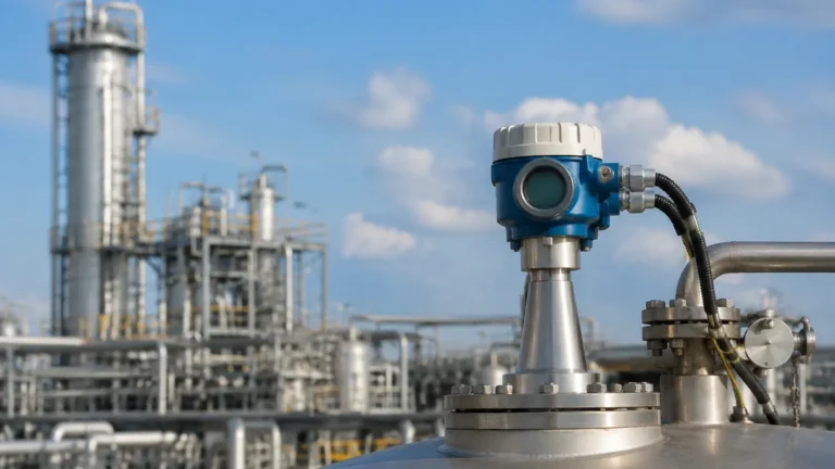
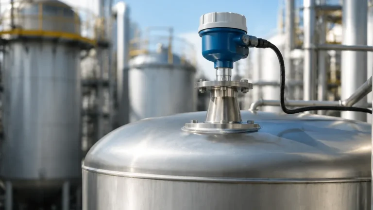
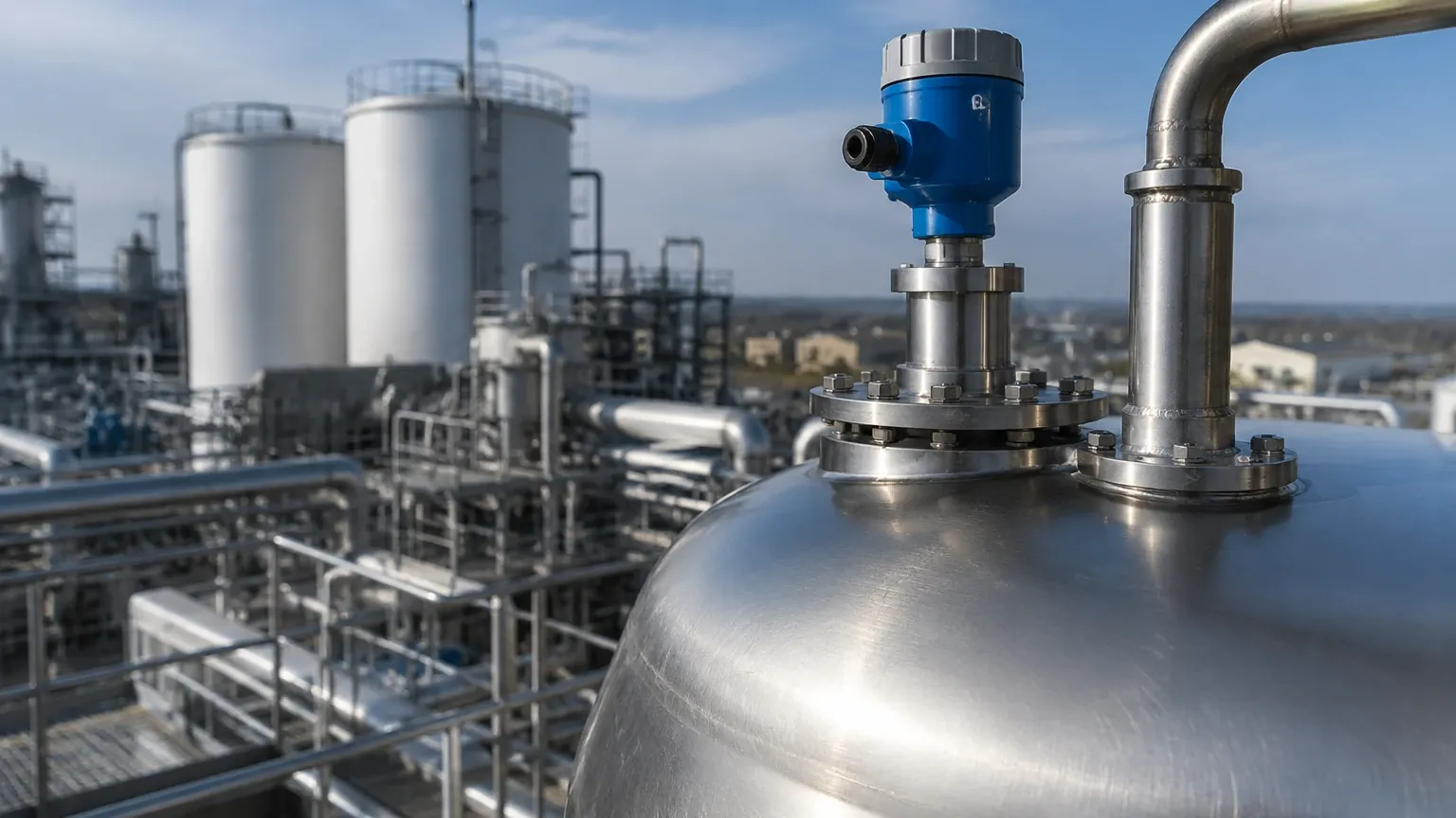
In the field of industrial process automation, selecting the appropriate level measurement technology is critical for operational safety, inventory accuracy, and process efficiency. Among the various technologies available, the non guided radar level transmitter stands out as a versatile, non-contact solution capable of handling complex media and extreme environments. Unlike guided wave radar (GWR), which uses a physical probe to direct the signal, non-guided radar (NGR) transmits electromagnetic pulses through the air space of a vessel, making it ideal for applications where contact with the medium is prohibited or impractical.
This article provides a comprehensive engineering reference for Radar Level Meters, covering their fundamental measurement principles, selection criteria, installation requirements, and practical limitations.
Measurement Principles of Non-Guided Radar
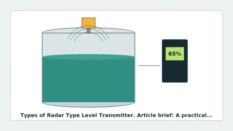
Non-guided radar level transmitters operate on the principle of electromagnetic wave reflection. The device emits high-frequency radar pulses (typically in the microwave spectrum) from an antenna. These waves travel at the speed of light through the vapor space, reach the surface of the product, and are reflected back to the sensor. The transmitter then calculates the distance to the product surface based on the time elapsed between transmission and reception.
There are two primary methods used in modern industrial radar systems:
1. Pulse Radar (Time of Flight)
Pulse radar transmitters emit short microwave pulses and measure the "Time of Flight" (ToF). Because the speed of light is constant, the distance is calculated using the formula:
*Distance = (Speed of Light × Time of Flight) / 2*.
Pulse radar is known for its energy efficiency and is often used in battery-powered or loop-powered applications. However, it may require more sophisticated signal processing to filter out noise in turbulent environments.
2. Frequency Modulated Continuous Wave (FMCW)
FMCW technology transmits a continuous signal with a constantly changing frequency (a frequency sweep). The reflected signal is received and compared to the signal being transmitted at that exact moment. The difference in frequency is directly proportional to the distance. FMCW radar generally offers higher accuracy (often within ±1 mm to ±2 mm) and better signal-to-noise ratios compared to pulse radar, making it the preferred choice for high-precision custody transfer and complex industrial tanks.
Key Components and Antenna Types
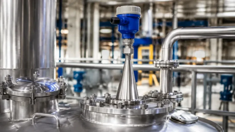
The performance of a non guided radar level transmitter is heavily influenced by its antenna design. The antenna serves as the interface between the electronic circuitry and the process environment.
* Horn Antennas: These are the most common industrial antennas. They are robust and suitable for a wide range of temperatures and pressures. Larger horn diameters result in narrower beam angles and stronger signals.
* Lens Antennas (Water-drop): Often made of PTFE or PP, these antennas have a smooth, curved surface that resists condensation and material buildup. They are frequently used in chemical storage and wastewater applications.
* Parabolic Antennas: These utilize a large dish to focus the radar beam. They provide the narrowest beam angles and the highest gain, making them suitable for very long-range measurements (up to 70 or 100 meters) in large silos or outdoor reservoirs.
Selection Criteria for Industrial Applications
Choosing the right radar transmitter requires an analysis of the process media, the vessel geometry, and the environmental conditions. Engineers should consider the following factors:
Operating Frequency
The frequency of the radar signal dictates the beam angle and the ability of the sensor to penetrate dust or steam.
| Frequency Range | Typical Beam Angle | Primary Applications | Strengths | Weaknesses |
| :— | :— | :— | :— | :— |
| C-Band (6-10 GHz) | 20° – 30° | Turbulent liquids, heavy foam, steam. | Excellent penetration of vapor and foam. | Large antenna size required; wide beam angle picks up tank wall interference. |
| K-Band (24-26 GHz) | 8° – 12° | Standard process tanks, small vessels. | Good balance of accuracy and size; standard for most industrial liquids. | Moderate sensitivity to heavy condensation. |
| W-Band (76-81 GHz) | 3° – 4° | Narrow tanks, solids, high-precision storage. | Extremely narrow beam; small process connections; high accuracy. | Reduced performance in very thick foam or heavy steam. |
Dielectric Constant (εr)
The dielectric constant of the medium determines how much of the radar signal is reflected. Materials with a high dielectric constant (e.g., water, εr ≈ 80) reflect signals strongly. Hydrocarbons and oils (low εr ≈ 1.9 to 4.0) reflect much weaker signals. For materials with εr < 1.5, non-guided radar may require specialized high-sensitivity electronics or the use of a stilling well to concentrate the signal.
Process Temperature and Pressure
Standard radar transmitters can handle temperatures from -40°C to +150°C. However, for high-temperature reactors or cryogenic storage, specialized thermal spacers and high-pressure seals (using ceramics or specialized polymers) are required to protect the electronics.
Installation Considerations and Best Practices
Correct installation is the single most important factor in ensuring the reliability of a non guided radar level transmitter. Because the signal travels through open space, any obstruction in the beam path can cause false echoes.
1. The 1/6 Diameter Rule: For vertical cylindrical tanks, the transmitter should generally be installed at a distance of 1/6th of the tank diameter from the side wall. Installing it too close to the wall causes signal interference, while installing it in the dead center can lead to multiple reflections (focusing effect) from the tank roof.
2. Nozzle Height and Diameter: The antenna should ideally extend slightly beyond the bottom of the mounting nozzle. If the nozzle is too long or narrow, the radar signal will reflect off the nozzle walls before even entering the tank, creating a "near-field" interference zone.
3. Avoiding Obstructions: The radar beam path must be clear of internal structures such as agitators, heating coils, ladders, and support beams. If an obstruction is unavoidable, many modern transmitters offer "False Echo Suppression" software that allows the user to map out and ignore these static reflections.
4. Beam Angle Calculation: Engineers must calculate the "footprint" of the radar beam at the lowest point of the tank to ensure it does not hit the tank wall or the discharge outlet. The footprint diameter can be calculated as: *D = 2 × Distance × tan(Beam Angle / 2)*.
Limitations and Risk Mitigation
While highly versatile, non-guided radar is not a universal solution. Engineers must be aware of the following limitations:
* Heavy Foam: Thick, dense foam can absorb the radar signal entirely, leading to a loss of echo. In such cases, low-frequency (6 GHz) radar or guided wave radar may be more effective.
* Dust and Solids: In powder or grain silos, dust clouds can attenuate high-frequency signals. Furthermore, solids do not form a flat surface; the "angle of repose" can deflect the radar signal away from the receiver. High-power 80 GHz transmitters with specialized algorithms are typically used to overcome these challenges.
* Extreme Condensation: While many antennas are designed to shed droplets, heavy condensation on the antenna lens can cause signal attenuation. Air purging systems can be integrated to keep the antenna face clean and dry.
Comparison: Non-Guided vs. Guided Wave Radar
| Feature | Non Guided Radar (NGR) | Guided Wave Radar (GWR) |
| :— | :— | :— |
| Contact | Non-contact | Contact (Probe/Cable) |
| Maintenance | Low (no wear on probe) | Medium (probe cleaning/corrosion) |
| Internal Obstructions | Sensitive to beam path | Not sensitive (signal follows probe) |
| Foam Performance | Varies by frequency | Generally better (penetrates foam) |
| Installation | Easier (no probe to tension) | Requires probe length adjustment |
Frequently Asked Questions (FAQs)
Q: Can a non guided radar level transmitter measure through a plastic tank roof?
A: Yes. Since microwaves can penetrate non-conductive materials like polyethylene or fiberglass, the transmitter can be mounted outside the tank, looking through the roof. This is common in chemical IBCs or small plastic storage tanks, provided the roof material is not too thick and does not contain metal reinforcement.
Q: How does agitation affect the measurement?
A: Surface turbulence caused by agitators can scatter the radar signal. However, by using FMCW technology and adjusting the software's damping settings, the transmitter can average out the fluctuations to provide a stable level reading. In extreme cases, a stilling well (a vertical pipe) is used to create a calm surface for measurement.
Q: Is calibration required for different media?
A: Generally, no. Unlike capacitive sensors, radar measures distance based on time or frequency shift, which is independent of the medium's density or conductivity (as long as the dielectric constant is sufficient to provide a reflection).
Conclusion
The non guided radar level transmitter is a cornerstone of modern industrial level measurement. By understanding the nuances of frequency selection, antenna design, and installation geometry, engineers can implement a maintenance-free solution that performs reliably in the most demanding environments. Whether monitoring corrosive chemicals, high-temperature bitumen, or simple water reservoirs, these instruments provide the precision necessary for advanced process control.
For more detailed technical specifications and to explore specific hardware configurations for your facility, you may Review product options and application support to find the ideal match for your process requirements.