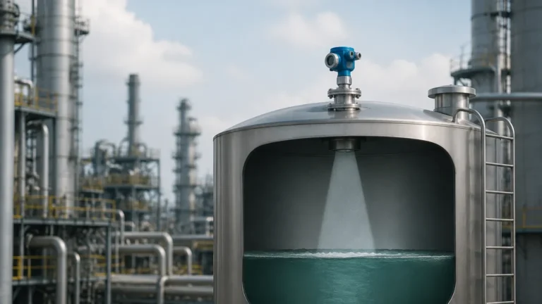
Radar Level Transmitter 5408
Radar Level Transmitter 5408: A Technical Guide to High-Performance Level Measurement
In the landscape of industrial automation, accurate and reliable level measurement is a cornerstone of process efficiency and safety. The radar level transmitter 5408 represents a significant advancement in non-contacting level measurement technology. Designed to meet the rigorous demands of the chemical, oil and gas, and power industries, this instrument utilizes Frequency Modulated Continuous Wave (FMCW) technology to provide precise readings even in the most challenging process conditions. This guide explores the engineering principles, selection criteria, and installation best practices for the 5408 series, providing a comprehensive reference for instrumentation engineers and procurement specialists.
Understanding the Measurement Principle: FMCW Technology
Unlike traditional pulse-based radar systems that measure the time-of-flight of a single microwave pulse, the radar level transmitter 5408 employs FMCW technology. This principle is fundamental to its high accuracy and reliability.
How FMCW Works
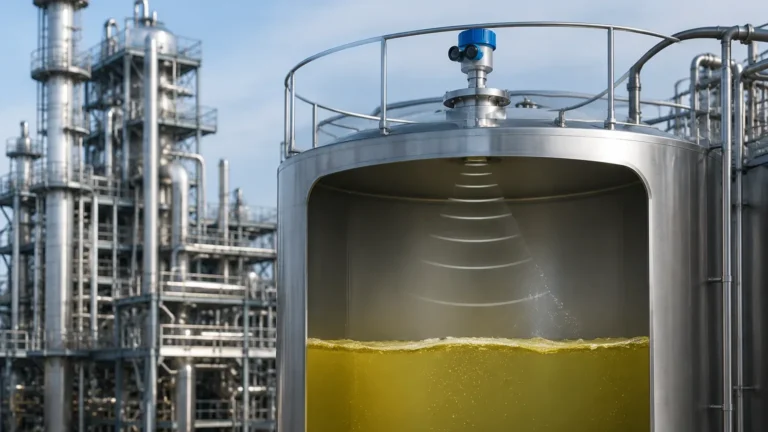
In an FMCW system, the transmitter emits a continuous signal with a constantly changing frequency (a frequency sweep). This signal travels to the surface of the product, reflects, and returns to the antenna. Because the transmitter is continuously sweeping the frequency, by the time the reflected signal returns, the transmitted frequency has shifted.
The difference between the transmitted frequency and the received frequency is directly proportional to the distance the signal has traveled. By performing a Fast Fourier Transform (FFT) on this frequency difference, the device can accurately calculate the distance to the product surface.
Advantages of FMCW
1. Higher Signal-to-Noise Ratio: Continuous emission provides more energy to the process than pulse systems, allowing for a clearer signal even through turbulence or foam.
2. Superior Accuracy: FMCW allows for a much finer resolution of the signal, typically achieving accuracies within ±2 mm (0.08 in).
3. Better Handling of Low Dielectrics: The increased sensitivity makes it possible to measure liquids with low dielectric constants (εr), which are traditionally difficult for radar instruments.
When evaluating high-performance Radar Level Meters, understanding this shift from pulse to FMCW is critical for selecting the right technology for complex tank geometries.
Key Features and Engineering Advantages of the 5408 Series
The 5408 series is engineered for ease of use and long-term reliability. Its design focuses on reducing the total cost of ownership through simplified commissioning and robust hardware.
* Two-Wire Loop Powered: The device operates on a standard 4-20 mA HART loop, simplifying wiring and integration into existing control systems.
* Safety Integrity Level (SIL): The 5408:SIS version is specifically designed for safety-instrumented systems, certified to SIL 2 (capable of SIL 3 in redundant configurations) according to IEC 61508.
* EchoLogics Technology: This advanced signal processing algorithm helps the transmitter distinguish between the actual product level and false echoes caused by internal tank obstructions like agitators, heating coils, or baffles.
* Human-Centered Design: The software interface provides intuitive wizards for setup, reducing the need for specialized training during commissioning.
Technical Specifications and Selection Criteria
Selecting the correct configuration for a radar level transmitter 5408 requires a detailed understanding of the process environment. The following parameters are essential for technical specification:
1. Process Temperature and Pressure
Standard models typically handle temperatures from -60°C to +250°C (-76°F to +482°F) and pressures up to 100 bar (1450 psi). For extreme conditions, specialized seals and cooling fins may be required.
2. Antenna Type
The antenna is the interface between the instrument and the process. The choice depends on the media and the tank nozzle size:
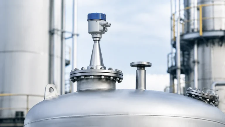
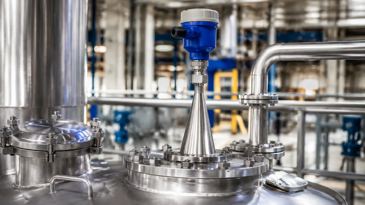
* Cone Antenna: Ideal for most liquid applications; available in various sizes to match nozzle diameters.
* Process Seal Antenna: Features a flush-mounted PTFE or PEK seal, making it suitable for corrosive media or hygienic applications where product buildup must be prevented.
* Parabolic Antenna: Used for long-range measurements (up to 40 meters / 131 ft) or when measuring solids with low reflectivity.
3. Material Compatibility
Wetted parts are commonly available in 316/316L Stainless Steel, Alloy C-276, or Alloy 400. The choice must be dictated by the chemical properties of the measured fluid to prevent corrosion.
Selection Table for Industrial Applications
| Application | Recommended Antenna | Material | Key Consideration |
| :— | :— | :— | :— |
| Acid Storage Tanks | Process Seal Antenna | PTFE / Alloy C-276 | Corrosion resistance and flush mounting to prevent buildup. |
| Oil/Water Separators | Cone Antenna | 316L Stainless Steel | High accuracy required for interface detection. |
| Large Solids Silos | Parabolic Antenna | 316L Stainless Steel | High gain needed for dispersed signals on uneven surfaces. |
| Agitated Vessels | Cone Antenna with Still Pipe | 316L Stainless Steel | Minimizing surface turbulence for a stable reading. |
| Hygienic Food/Beverage | Tri-Clamp Process Seal | Polished 316L / PTFE | Compliance with 3-A or EHEDG standards. |
Installation Guidelines and Geometric Constraints
Correct installation is the most influential factor in the performance of any radar level meter. For the radar level transmitter 5408, several geometric rules must be followed to ensure signal integrity.
Nozzle Considerations
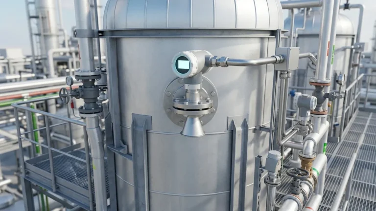
* Nozzle Height: The antenna should ideally extend slightly below the nozzle to prevent internal reflections. If the nozzle is very long, a nozzle extension or a specific antenna design may be necessary.
* Nozzle Diameter: Ensure the antenna diameter is slightly smaller than the nozzle ID to allow for easy insertion without damaging the seals.
Positioning and Obstructions
* Avoid the Center: Never mount the transmitter in the center of a dome-roof tank. This can cause multiple reflections that interfere with the primary signal.
* Distance from Wall: The transmitter should be mounted at a distance of approximately 1/6th to 1/4th of the tank diameter from the wall to avoid interference from wall effects while staying clear of the center.
* Internal Obstacles: The radar beam is cone-shaped. Ensure that there are no pipes, ladders, or agitators within the beam path. If obstructions are unavoidable, the device's "False Echo Suppression" feature must be used during commissioning.
Mounting Angle
The transmitter must be mounted vertically (perpendicular to the liquid surface). For solids applications where the material forms a cone, an adjustable swivel flange may be used to aim the radar beam at the most representative part of the slope.
Handling Process Challenges: Foam, Agitation, and Vapors
While FMCW technology is robust, certain process conditions require additional engineering considerations:
1. Foam: Light, airy foam can sometimes be transparent to radar, while dense, thick foam can absorb or reflect the signal prematurely. In cases of heavy foam, using a lower frequency radar or a stilling well is recommended.
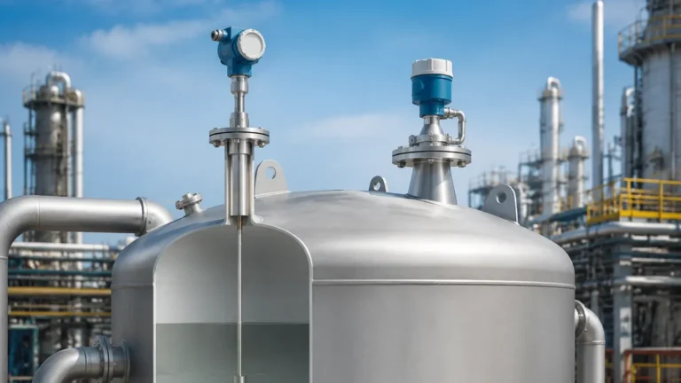
2. Agitation: Rapidly moving surfaces create "noise." The 5408 handles this through signal averaging and its high-update rate, but a stilling well is the most effective mechanical solution for extreme turbulence.
3. Vapors and Condensation: While radar is generally unaffected by vapors, heavy condensation on the antenna lens can attenuate the signal. Process seal antennas with PTFE faces are designed to shed droplets effectively.
Maintenance and Verification Procedures
One of the primary benefits of the radar level transmitter 5408 is its low maintenance requirement due to the lack of moving parts. However, regular verification is necessary for quality assurance and safety compliance.
* Remote Proof Testing: For SIS applications, the 5408 allows for remote proof testing. This means the functionality of the device can be verified from the control room without needing to remove the device or manually change the liquid level.
* Signal Quality Metrics: The transmitter provides a "Signal Quality" diagnostic. A decreasing trend in signal quality over time may indicate product buildup on the antenna or a change in the process (e.g., increased foaming), allowing for predictive maintenance.
* Cleaning: If the media is prone to crystallization or heavy coating, periodic inspection of the antenna is required. Using a process seal antenna usually minimizes the frequency of cleaning.
Frequently Asked Questions (FAQ)
Q: Can the radar level transmitter 5408 measure solids?
A: Yes, it is highly effective for solids measurement. However, for very dusty environments or materials with a low dielectric constant like plastic pellets, a parabolic antenna is often preferred to maximize signal return.
Q: What is the minimum dielectric constant (D.C.) the 5408 can measure?
A: With FMCW technology and advanced signal processing, the 5408 can typically measure media with a dielectric constant as low as 1.2, provided the surface is relatively calm.
Q: Is a stilling well required for all applications?
A: No. Stilling wells are only necessary for applications with extreme turbulence, heavy foam, or when the tank has too many internal obstructions that cannot be mapped out electronically.
Q: How does the 5408 handle vacuum conditions?
A: Radar technology is ideal for vacuum because the microwave signal does not require a medium (like air) to travel. The selection of the process seal and flange rating is the primary concern for vacuum applications.
Conclusion
The radar level transmitter 5408 is a versatile and highly capable instrument that addresses the complexities of modern industrial level measurement. By utilizing FMCW technology, it provides a level of precision and reliability that pulse-based systems often struggle to match. For engineers, successful implementation relies on a thorough understanding of the process chemistry, tank geometry, and the specific strengths of the various antenna configurations available. When properly specified and installed, these instruments provide years of maintenance-free service, contributing significantly to plant safety and operational excellence.