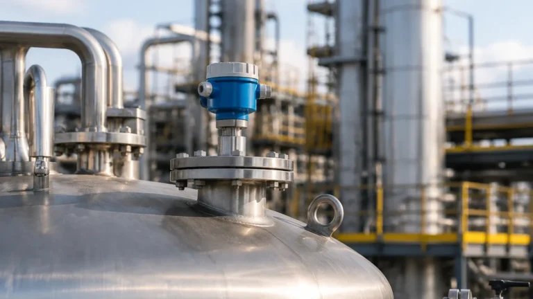
Krohne Guided Wave Radar Level Transmitter
Engineering Guide to Krohne Guided Wave Radar Level Transmitters
In the landscape of industrial process automation, achieving precise level measurement is critical for safety, inventory management, and process efficiency. Among the various technologies available, Guided Wave Radar (GWR) has emerged as one of the most versatile and reliable methods for both liquid and solid applications. As a pioneer in Time Domain Reflectometry (TDR), the Krohne guided wave radar level transmitter series represents a significant segment of the high-end instrumentation market.
This guide provides a technical overview of GWR technology, specific considerations for selecting Krohne-style instrumentation, and practical installation advice for engineers and procurement professionals. For those evaluating a broader range of technologies, comparing these systems with other Radar Level Meters is essential to ensure the chosen solution meets specific site requirements and budget constraints.
1. Measurement Principle: Time Domain Reflectometry (TDR)
Before selecting a specific krohne guided wave radar level transmitter, it is vital to understand the underlying physics. GWR instruments operate based on the principle of Time Domain Reflectometry (TDR), which was originally developed to locate breaks in underground cables.
How TDR Works
The transmitter emits a series of low-intensity, high-frequency electromagnetic pulses. These pulses are guided along a physical probe (the waveguide), which is submerged in the process medium. When the pulse reaches the surface of the product, a portion of the pulse energy is reflected back to the transmitter. This reflection occurs because of the change in the dielectric constant ($ε_r$) between the upper medium (usually air or gas) and the lower medium (the liquid or solid being measured).
The electronics within the transmitter measure the time-of-flight—the nanosecond interval between the pulse emission and the reception of the reflected signal. Since the speed of light is constant in a vacuum (and nearly constant in air), the distance to the product surface can be calculated with extreme precision.
The Role of the Dielectric Constant
The dielectric constant of the medium determines the strength of the reflection.
- High Dielectric Media: Water ($ε_r ≈ 80$) provides a very strong reflection, making it easy to measure.
- Low Dielectric Media: Hydrocarbons and oils ($ε_r ≈ 1.9$ to $4.0$) reflect less energy. In these cases, more sensitive electronics or specific probe designs (like coaxial probes) are required to capture the signal.
2. The Krohne Optiflex Series Overview
Krohne categorizes its GWR transmitters under the "Optiflex" brand. Each model is engineered for specific industrial challenges, ranging from basic water storage to high-pressure steam applications.
* Optiflex 1100: Designed for non-hazardous areas and basic liquid/solid applications. It is often used in the water and wastewater industry.
* Optiflex 1300: A versatile device for more demanding processes, capable of handling higher temperatures and pressures.
* Optiflex 3200: Specifically designed for the pharmaceutical and food industries, featuring hygienic connections and polished surfaces.
* Optiflex 7200/8200: High-end models designed for extreme temperatures (up to +315°C / +599°F) and high pressures (up to 320 bar / 4641 psi), frequently found in oil and gas or power generation.
3. Selection Criteria for GWR Instrumentation
Selecting the correct krohne guided wave radar level transmitter requires a deep dive into the process conditions. The following table outlines how probe selection impacts performance across different media.
Table 1: Probe Selection and Application Suitability
| Probe Type | Best For | Advantages | Limitations |
| :— | :— | :— | :— |
| Single Rod/Cable | Viscous liquids, solids, wastewater | Resists buildup; easy to clean | Sensitive to internal tank obstructions; requires higher $ε_r$ |
| Double Rod/Cable | Clean liquids with lower $ε_r$ | Better signal focus than single rod | Prone to bridging if solids or sticky media are present |
| Coaxial Probe | Low dielectric liquids ($ε_r > 1.4$), turbulent surfaces | Highest signal-to-noise ratio; immune to tank internals | Only for clean, low-viscosity liquids; difficult to clean |
Key Considerations
1. Measuring Range: Cables can extend up to 60 meters (approx. 197 ft), while rods are typically limited to 6 meters (approx. 20 ft) due to shipping and installation constraints.
2. Process Temperature and Pressure: Ensure the flange and seal materials (e.g., FKM, Kalrez, or Ceramic) are compatible with the chemical composition and temperature of the vessel.
3. Interface Measurement: GWR is uniquely suited for measuring the interface between two liquids (e.g., oil over water). This requires the upper liquid to be non-conductive and have a lower dielectric constant than the bottom liquid.
4. Installation Considerations and Constraints
Proper installation is the most critical factor in the long-term reliability of any Radar Level Meters. For guided wave radar, the physical probe must be managed correctly within the vessel.
Nozzle Geometry
The nozzle diameter and height can affect the signal near the top of the tank. If the nozzle is too narrow or too tall, it may create parasitic reflections. Standard GWR units typically require a nozzle diameter of at least 50 mm (2 inches) for rod probes, though coaxial probes are less sensitive to nozzle dimensions.
Clearance from Tank Walls and Internals
For single rod or cable probes, a minimum clearance from the tank wall and internal obstructions (like ladders or agitators) must be maintained. A general rule is to maintain at least 300 mm (12 inches) of clearance to prevent the signal from "jumping" to the metal wall, which would result in a false level reading.
The "Dead Zone" (Blocking Distance)
Every GWR transmitter has an upper and lower dead zone.
- Upper Dead Zone: The area near the flange where the pulse is still stabilizing. Measurements in this zone are unreliable.
- Lower Dead Zone: The area at the very tip of the probe where the signal may be lost or distorted by the tank bottom.
Engineers must ensure that the expected operating range of the tank falls between these two zones.

5. Application Risks and Limitations
While GWR is robust, it is not a "one-size-fits-all" solution. International buyers should be aware of the following risks:
* Media Buildup: While single-rod probes handle coating better than others, extreme buildup of conductive or damp material can attenuate the signal, leading to "signal lost" errors.
* Mechanical Stress: In tall silos containing heavy solids (like grain or sand), the pull-down forces on a cable probe can be immense. The roof of the silo and the probe's tensile strength must be rated for these loads.
* Foam: Dense, thick foam can sometimes reflect the signal, while light, airy foam might be transparent to the radar. If the goal is to measure the liquid level *under* the foam, GWR is usually superior to non-contact radar, but testing is often required.
6. Buyer’s Confirmation Checklist
When requesting a quote for a krohne guided wave radar level transmitter, ensure the following data points are confirmed with the manufacturer or supplier:
1. Product Dielectric Constant: Is it above 1.4? If lower, a coaxial probe or a specialized high-sensitivity unit is required.
2. Vessel Drawing: Provide a top-down and side-view drawing showing nozzles, agitators, and heating coils.
3. Material Compatibility: Confirm that the probe material (316L Stainless Steel, Hastelloy, etc.) and the gaskets are compatible with the process fluid.
4. Hazardous Area Ratings: Does the site require ATEX, IECEx, or FM approvals (Intrinsically Safe or Explosion-Proof)?
5. Output Protocol: Standard 4-20mA with HART is common, but Foundation Fieldbus, Profibus PA, or Modbus may be required for modern digital architectures.
7. Frequently Asked Questions (FAQ)
Q: Can GWR measure levels in a plastic tank?
A: Yes. However, since there is no metal tank top to act as a ground plane, a special mounting plate or a coaxial probe may be required to ensure signal stability.
Q: How does GWR compare to ultrasonic level sensors?
A: GWR is generally superior in processes with dust, steam, or vacuum conditions, as electromagnetic pulses do not require a medium (air) to travel, whereas ultrasonic waves are sound-based and affected by air density and temperature.
Q: Is it possible to shorten a cable probe on-site?
A: Most krohne guided wave radar level transmitter models allow for field-shortening of the cable. However, the transmitter's software must be updated with the new probe length to maintain accuracy.
Q: Does the probe need to touch the bottom of the tank?
A: No. In fact, it is often recommended to leave a small gap (approx. 50-100 mm) to avoid mechanical damage from tank expansion or sediment buildup, unless the probe is being used for bottom-anchoring in turbulent liquids.
Conclusion
The krohne guided wave radar level transmitter is a high-performance instrument capable of solving complex level measurement challenges in the chemical, oil and gas, and power industries. By understanding the TDR principle and carefully selecting the probe type based on the dielectric constant and vessel geometry, engineers can implement a maintenance-free solution. For more information on alternative technologies or to compare technical specifications, exploring various Radar Level Meters will provide the necessary context for a successful installation.
Download Krohne Guided Wave Radar Level Transmitter as a PDF