Radar Level 2
Radar Level 2
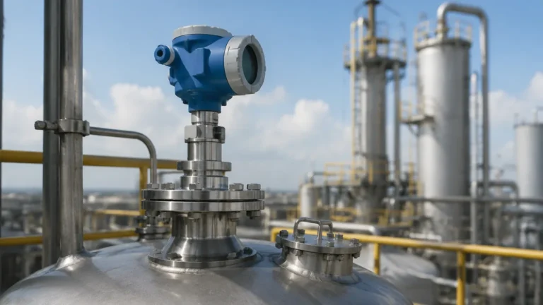
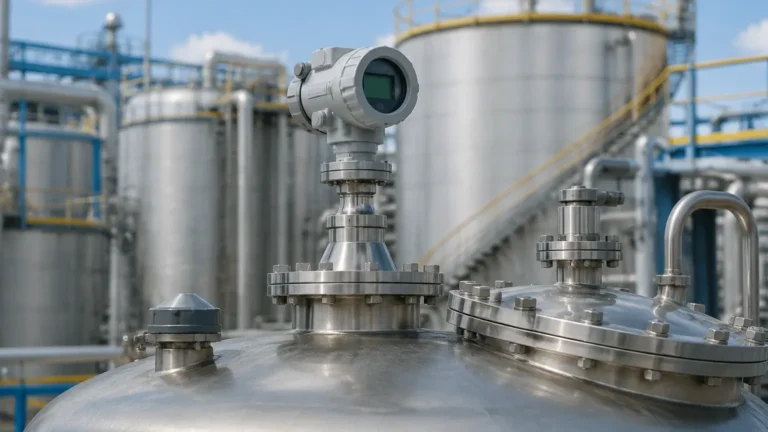
In the landscape of industrial process automation, precise inventory management and process control depend heavily on reliable level measurement. Among the various technologies available, radar-based systems have emerged as the industry standard for challenging environments. This guide explores the technical nuances of radar level measurement, specifically focusing on the engineering requirements for "radar level 2" tier instrumentation—systems designed for high accuracy, complex geometries, and volatile process conditions.
Understanding Radar Level Measurement Principles
Before selecting a specific instrument, it is essential to understand the physics governing radar technology. Radar level meters operate by emitting electromagnetic pulses or continuous waves toward a material surface and measuring the reflected signal.
Time of Flight (ToF) vs. FMCW
There are two primary methods used in industrial radar level measurement:
1. Pulse Radar (ToF): The instrument emits a short microwave pulse. The time it takes for the pulse to travel to the surface and back is measured. Since the speed of light is constant, the distance is calculated as:
*Distance = (Speed of Light × Time of Flight) / 2*
2. Frequency Modulated Continuous Wave (FMCW): The instrument emits a continuous signal with a constantly changing frequency. The frequency difference between the transmitted signal and the reflected signal is proportional to the distance. FMCW is generally preferred for high-precision applications due to its superior signal-to-noise ratio and ability to filter out interference.
The Role of Dielectric Constant (εr)
The dielectric constant of the medium is the most critical factor in radar measurement. It determines how much of the electromagnetic energy is reflected back to the sensor. Materials with high dielectric constants, such as water (εr ≈ 80), provide strong reflections. Conversely, materials like hydrocarbons, oils, or plastic pellets have low dielectric constants (εr < 2.5), which absorb or transmit more energy, resulting in weaker return signals. Modern Radar Level Meters utilize advanced algorithms to amplify these weak signals, ensuring reliable measurement even in low-dielectric media.
Technical Selection Criteria for Radar Level 2 Systems
Selecting the correct radar instrument requires an evaluation of the process environment and the physical properties of the vessel. The following table summarizes the primary selection factors for industrial-grade radar sensors.
Selection Comparison Table
| Feature | 26 GHz Pulse Radar | 80 GHz FMCW Radar | Guided Wave Radar (GWR) |
| :— | :— | :— | :— |
| Measurement Range | Up to 30 meters | Up to 120 meters | Up to 75 meters |
| Accuracy | ±3 mm to ±5 mm | ±1 mm | ±2 mm to ±5 mm |
| Beam Angle | 8° to 20° (Wide) | 3° to 8° (Narrow) | N/A (Contacting) |
| Surface Conditions | Moderate foam/turbulence | Heavy dust/agitation | Minimal turbulence |
| Mounting Size | 2" to 4" Nozzles | 1" to 3" Nozzles | 3/4" to 2" NPT/Flange |
| Best Use Case | Large tanks, liquids | Tall silos, narrow tanks | Low dielectric liquids |
Frequency Considerations
The frequency of the radar signal significantly impacts performance. Higher frequencies, such as 80 GHz, allow for smaller antenna sizes and narrower beam angles. A narrow beam is advantageous in vessels with internal obstructions like agitators, heating coils, or ladders, as it minimizes the risk of "false echoes" from these structures. Lower frequencies, such as 6 GHz or 26 GHz, are more robust in applications with heavy steam or condensation, as the longer wavelengths can penetrate vapor more effectively.
Installation Guidelines and Constraints
Correct installation is as vital as instrument selection. Even the most advanced radar level 2 system will fail if environmental constraints are ignored.
Nozzle Placement and Geometry
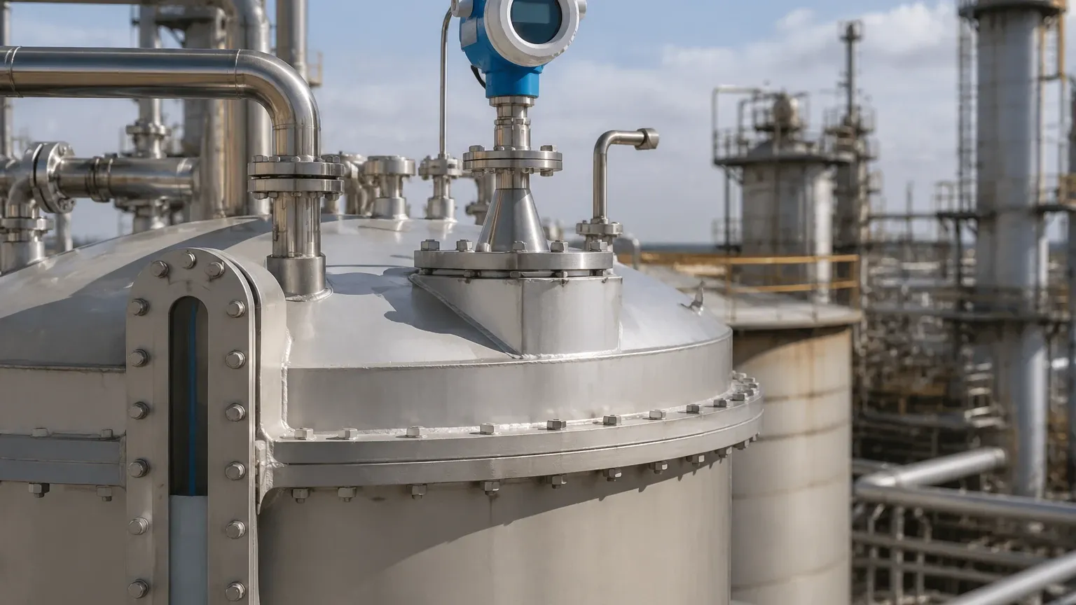
* Avoid the Center: Never install a radar sensor in the exact center of a domed or cylindrical tank. This can cause multiple reflections to converge, creating a "false peak" that overwhelms the actual level signal.
* Wall Distance: Maintain a minimum distance from the tank wall, typically 1/10th of the tank height or at least 200 mm. Installing too close to the wall can cause signal attenuation.
* Nozzle Height: The nozzle should be as short as possible. If the nozzle is too long, the radar signal may reflect off the internal edges of the nozzle before entering the tank, creating a large "blind zone" at the top of the vessel.
Obstruction Management
Internal structures like pipes or mixers can reflect signals. If an obstruction cannot be avoided, engineers should use "False Echo Suppression" or "Echo Mapping." This software feature allows the Welk radar meter to record the static reflections of the empty tank and ignore them during active measurement.
Application-Specific Challenges
Turbulence and Foam
Turbulent surfaces scatter radar signals, reducing the strength of the return echo. In such cases, an FMCW radar with a high dynamic range is required. Foam presents a unique challenge; dry, thick foam can reflect the signal (measuring the top of the foam), while wet, thin foam may be transparent to the radar. For extremely heavy foam, guided wave radar or hydrostatic transmitters may be more appropriate alternatives.
High Temperature and Pressure
In chemical processing or oil refining, temperatures can exceed 400°C and pressures can reach 160 bar. Radar level 2 instruments for these environments must be equipped with specialized ceramic or PTFE seals and cooling fins to protect the electronics from thermal damage.
Maintenance and Troubleshooting
While non-contact radar is inherently low-maintenance due to the lack of moving parts, certain conditions require periodic inspection:
1. Antenna Buildup: In applications involving sticky resins or heavy dust, material can accumulate on the antenna (lens). While many Welk radar meters feature "Air Purge" connections to blow away dust, manual cleaning may be necessary if the signal strength drops significantly.
2. Condensation: Heavy condensation can form droplets on the antenna. Choosing a radar with a convex lens design allows droplets to run off, preventing signal blockage.
3. Signal Loss: If the instrument reports "Signal Lost," check for changes in the dielectric constant of the medium or excessive foam that may be absorbing the signal.
Frequently Asked Questions (FAQ)
Q: Can radar measure the level through a plastic tank wall?
A: Yes. Because plastic has a low dielectric constant, radar signals can penetrate the walls of polyethylene or fiberglass tanks, allowing for non-intrusive measurement from the outside.
Q: What is the "Blind Zone" (Blocking Distance)?
A: The blind zone is the area immediately below the antenna where the instrument cannot accurately measure. This is typically between 50 mm and 300 mm, depending on the frequency and antenna design. The tank should never be filled into this zone.
Q: How does dust affect 80 GHz radar?
A: High-frequency 80 GHz radar is exceptionally good at penetrating dust in silos. Because the wavelength is small, it is not easily scattered by typical solid particles, making it ideal for cement, flour, or grain storage.
Q: Is calibration required for radar level meters?
A: Unlike hydrostatic or ultrasonic sensors, radar meters do not require frequent recalibration. They measure distance based on the speed of light, which is a physical constant. Users only need to configure the tank height and the 4-20mA/HART output scaling.
Conclusion for International Buyers
When sourcing radar level 2 instrumentation for global industrial projects, it is imperative to confirm the chemical compatibility of the wetted parts (typically 316L Stainless Steel, PTFE, or Hastelloy) and the required hazardous area certifications (ATEX, IECEx, or UL).
By prioritizing high-frequency FMCW technology and ensuring proper installation geometry, plant engineers can achieve millimetric accuracy in even the most demanding process conditions. For detailed technical specifications and model comparisons, engineers should Review product options and application support to match the specific dielectric and environmental requirements of their facility.