Radar Level Measurement Dielectric Constant
Radar Level Measurement Dielectric Constant: An Engineering Guide
In the field of industrial automation, radar technology has become the preferred choice for continuous level monitoring due to its non-contact nature and reliability in harsh environments. However, the performance of any radar-based system is fundamentally governed by the electrical properties of the medium being measured. Specifically, the radar level measurement dielectric constant ($ε_r$) is the most critical parameter in determining signal reliability, measurement accuracy, and the selection of appropriate instrumentation.
For process engineers and procurement specialists, understanding how the dielectric constant interacts with electromagnetic waves is essential for ensuring the long-term stability of level control systems. This guide examines the principles of radar reflection, the impact of dielectric properties on different radar technologies, and practical selection criteria for industrial applications.
1. Measurement Principles and the Role of Dielectric Constant
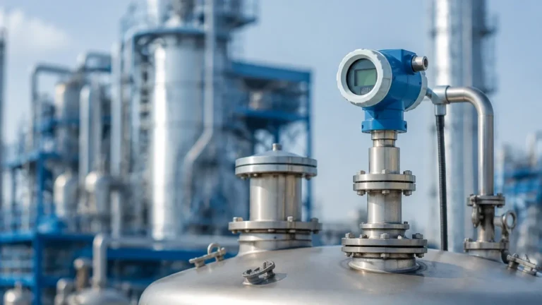
Radar level transmitters operate by emitting electromagnetic pulses or continuous wave signals toward a target material. These waves travel through the vapor space (usually air or nitrogen) and are reflected back to the sensor when they encounter a change in the dielectric constant at the surface of the medium.
The Physics of Reflection
The dielectric constant, also known as relative permittivity, is a dimensionless measure of a material's ability to store electrical energy in an electric field. In the context of Radar Level Meters, it determines the "reflectivity" of the surface.
When a radar wave hits the interface between two media with different dielectric constants (e.g., air and oil), a portion of the energy is reflected, while the remainder penetrates the medium. The reflection coefficient ($R$) can be simplified for normal incidence as:
$$R = \frac{\sqrt{ε_{r2}} – \sqrt{ε_{r1}}}{\sqrt{ε_{r2}} + \sqrt{ε_{r1}}}$$
Where:
* ε_{r1}: Dielectric constant of the upper medium (typically air ≈ 1.0).
* ε_{r2}: Dielectric constant of the process medium.
Materials with a high dielectric constant, such as water (ε_r ≈ 80), reflect a large percentage of the radar signal, resulting in a strong, easily detectable echo. Conversely, materials with low dielectric constants, such as hydrocarbons, liquefied gases, or plastic pellets (ε_r < 2.0), reflect very little energy, making the signal harder to distinguish from background noise.
2. Understanding Dielectric Values in Industrial Media
To select the correct instrument, engineers must know the approximate dielectric constant of their process medium. Industrial materials generally fall into three categories based on their ε_r values:
High Dielectric Media (ε_r > 10)
These materials are the easiest to measure. They provide a robust reflection even in the presence of surface turbulence or long measurement distances. Examples include:
* Water and water-based solutions (ε_r ≈ 80)
* Acids and alkalis (e.g., Sulfuric acid ε_r ≈ 84)
* Alcohols (e.g., Ethanol ε_r ≈ 24)
Medium Dielectric Media (ε_r 3 to 10)
These materials provide a moderate reflection. Standard non-contact radar units usually perform well here, though antenna selection becomes more important. Examples include:
* Grain and seeds (ε_r ≈ 3–5)
* Edible oils (ε_r ≈ 3)
* Dry cement (ε_r ≈ 4–6)
Low Dielectric Media (ε_r 1.4 to 3)
These materials present the greatest challenge for radar level measurement. The weak reflection requires high-sensitivity electronics and specialized antenna designs. Examples include:
* Diesel and fuel oils (ε_r ≈ 2.1)
* Liquefied petroleum gas (LPG) (ε_r ≈ 1.6–1.9)
* Plastic resins and powders (ε_r ≈ 1.5–2.5)
* Solvents like Hexane (ε_r ≈ 1.9)
3. Radar Technology Comparison: Pulsed vs. FMCW
When dealing with varying radar level measurement dielectric constant values, the choice between Pulsed Radar and Frequency Modulated Continuous Wave (FMCW) radar is significant.
Pulsed Radar
Pulsed radar emits short bursts of energy and measures the Time-of-Flight (ToF) for the echo to return. While energy-efficient, standard pulsed radar may struggle with very low dielectric materials over long distances because the peak power of the return signal may fall below the detection threshold.
FMCW Radar
FMCW radar emits a continuous signal with a varying frequency. By measuring the frequency difference between the emitted and received signal, the distance is calculated. FMCW generally offers a higher signal-to-noise ratio (SNR) and better resolution. This makes it the preferred choice for low dielectric constants, as the continuous integration of the signal allows the processor to "pull" a weak echo out of the noise more effectively.
4. Guided Wave Radar (GWR) vs. Non-Contact Radar
The dielectric constant also dictates whether a contact or non-contact approach is necessary.
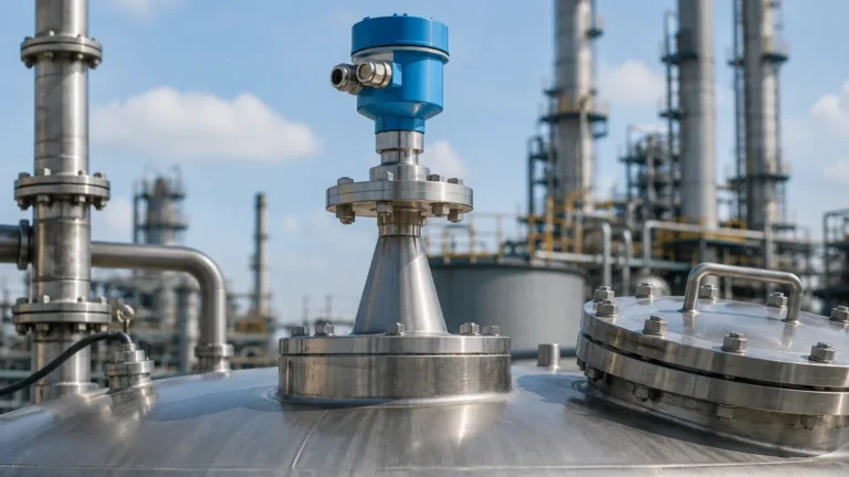
* Non-Contact Radar: Best for corrosive, hygienic, or extremely hot media. However, for low ε_r liquids, a large horn antenna or a parabolic antenna is often required to focus the beam and maximize the returned energy.
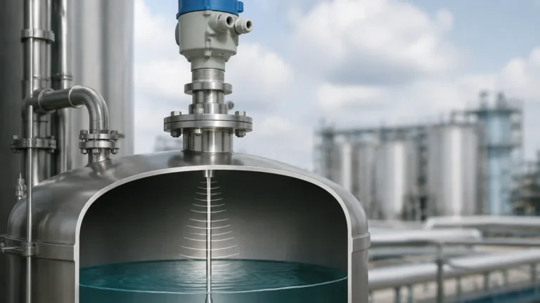
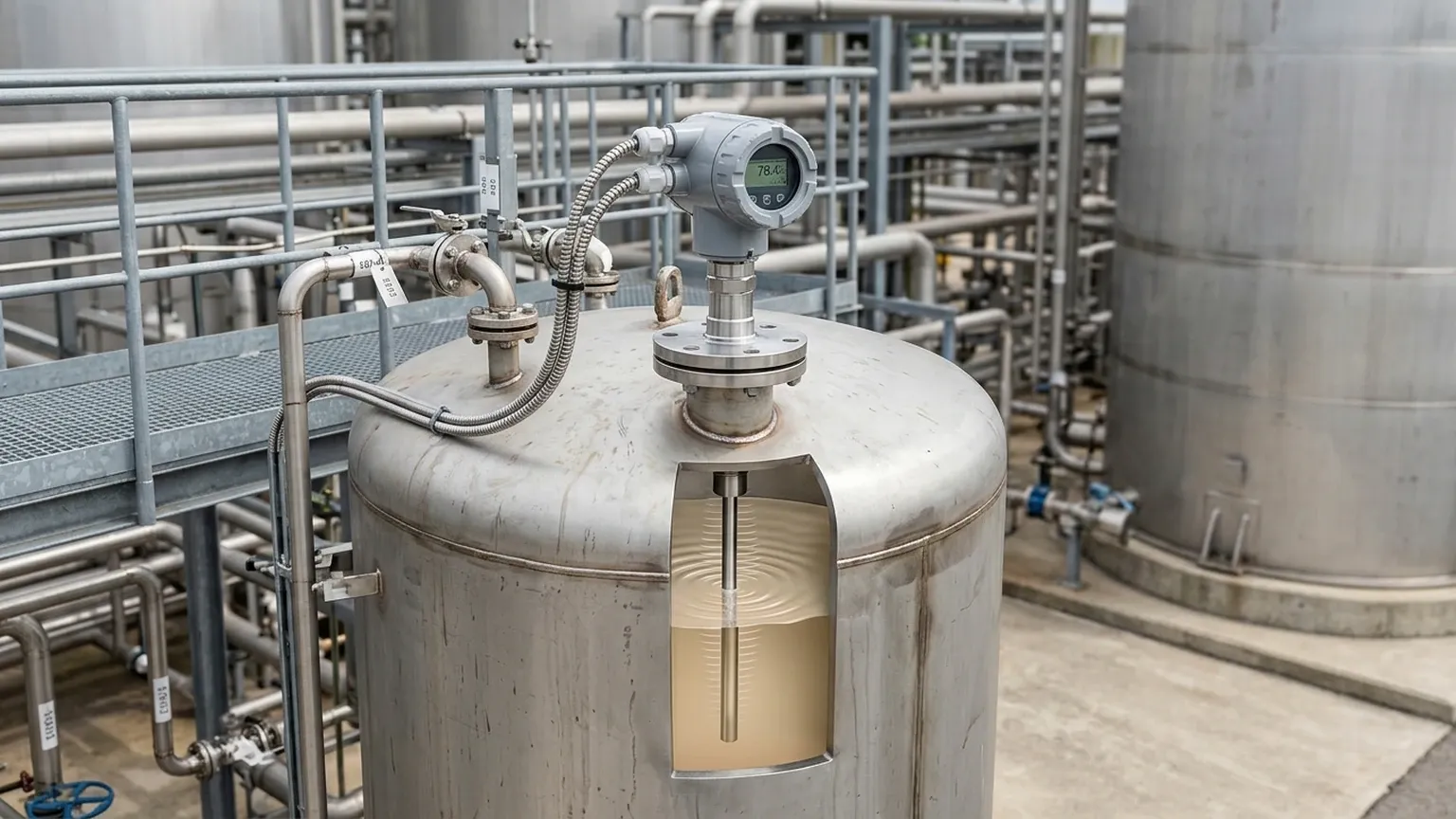
* Guided Wave Radar (GWR): GWR uses a physical probe (rod or cable) to guide the microwave signal. Because the energy is concentrated around the probe rather than spreading through space, GWR is significantly more efficient at measuring low dielectric materials. GWR can often measure media with ε_r as low as 1.4 without the need for specialized bypass chambers.
5. Selection Table for Industrial Applications
The following table provides a general guideline for selecting radar technology based on the medium's dielectric constant and process conditions.
| Dielectric Constant (ε_r) | Recommended Technology | Antenna/Probe Type | Typical Applications |
| :— | :— | :— | :— |
| > 10 | Non-Contact (80GHz or 26GHz) | Small Lens or Horn | Water tanks, chemical storage, wastewater |
| 3 to 10 | Non-Contact or GWR | Horn or Single Rod | Edible oils, dry bulk solids, molasses |
| 1.9 to 3 | High-Frequency Non-Contact or GWR | Large Horn or Coaxial Probe | Diesel, lube oils, plastic pellets |
| 1.4 to 1.9 | GWR or FMCW with Stilling Well | Coaxial Probe or Stilling Well | LPG, LNG, pure hydrocarbons, solvents |
6. Installation Considerations for Low Dielectric Media
When the radar level measurement dielectric constant is low, the physical installation of the sensor can compensate for the weak signal.
Stilling Wells and Bypass Pipes
For non-contact radar measuring low ε_r liquids, installing the sensor on a stilling well (a vertical pipe submerged in the liquid) is highly effective. The pipe acts as a waveguide, preventing the radar signal from dispersing and eliminating surface turbulence. This significantly increases the strength of the return signal.
Coaxial Probes in GWR
In GWR applications with very low dielectric constants (e.g., ε_r < 1.6), a coaxial probe is the gold standard. The outer tube of the coaxial probe contains the electromagnetic field entirely within the probe assembly, providing the highest possible signal sensitivity and immunity to tank internal obstructions.
Avoiding Obstructions
Low dielectric materials produce weak echoes that can easily be masked by "false echoes" from tank internals like agitators, ladders, or heating coils. When measuring low ε_r media, it is vital to install the radar unit in a position where the signal beam path is clear of any metallic structures.
7. Limitations and Application Risks
While radar is versatile, engineers should be aware of specific limitations related to dielectric properties:
1. Bottom Echo Interference: In tanks containing low dielectric liquids, the radar signal may pass through the liquid, reflect off the tank bottom, and return to the sensor. If the liquid level is low, the sensor might confuse the bottom reflection with the surface reflection. Advanced software (Bottom Echo Tracking) is often required to mitigate this.
2. Interface Measurement: Radar can measure the interface between two liquids (e.g., oil and water). For this to work, the upper layer must have a lower dielectric constant than the lower layer (e.g., oil over water), and the upper layer must be non-conductive to allow the signal to penetrate to the interface.
3. Variable Dielectric Constants: Some media change their ε_r based on temperature or composition. For example, the dielectric constant of steam increases with pressure, which can slow down the radar signal and cause a measurement error (though this is typically corrected via compensation algorithms in high-pressure boiler applications).
8. Frequently Asked Questions (FAQs)
Q: What is the minimum dielectric constant that a radar level meter can measure?
A: With modern high-sensitivity FMCW or Guided Wave Radar, measurements can be performed on materials with a dielectric constant as low as 1.4. Below this level, the signal reflection is generally too weak for reliable industrial use without a stilling well.
Q: How does foam affect radar measurement?
A: Foam is a mixture of air and liquid. If the foam is dry and has a low dielectric constant, the radar may see right through it to the liquid level. If the foam is thick, wet, and conductive (high dielectric), it may reflect the signal prematurely, leading to a false high-level reading. 80GHz radar is generally better at penetrating foam than lower frequency units.
Q: Can I use a radar meter if I don't know the dielectric constant of my product?
A: Yes, most modern Radar Level Meters feature auto-gain control and signal processing that can adapt to unknown media. However, for critical applications or low ε_r materials, it is always safer to consult the manufacturer's dielectric tables during the design phase.
Q: Does the dielectric constant affect the accuracy of the distance measurement?
A: In non-contact radar, the dielectric constant of the *vapor space* affects the speed of light and thus the accuracy. In most atmospheric tanks, this effect is negligible. However, in high-pressure gases, the dielectric constant of the gas increases, which can cause the radar to "over-read" the distance unless compensated.
9. Conclusion
The dielectric constant is the defining factor in the success of radar level applications. While high dielectric materials like water offer a forgiving environment for measurement, low dielectric hydrocarbons and solids require a more sophisticated engineering approach. By selecting the appropriate frequency, technology (FMCW vs. Pulsed), and installation method (stilling wells or GWR probes), reliable level measurement can be achieved in even the most challenging process conditions.
For international buyers and engineers, confirming the dielectric constant of the medium during the specification stage is the most effective way to prevent signal loss and ensure the long-term accuracy of industrial automation systems.
Download Radar Level Measurement Dielectric Constant as a PDF