Radar Level Sensor Vegapuls
Radar Level Sensor Vegapuls: An Engineering Guide to High-Frequency Level Measurement
In the landscape of industrial automation, the ability to accurately monitor liquid and solid levels is fundamental to process safety, inventory management, and operational efficiency. Among the various technologies available, non-contact radar has emerged as the gold standard for challenging environments. The radar level sensor vegapuls series has long been recognized as a benchmark in this field, representing a shift toward high-frequency microwave technology. For engineers and procurement specialists, understanding the technical nuances of these instruments—and how they compare to the broader category of Radar Level Meters—is essential for selecting the right equipment for specific process conditions.
This guide provides a comprehensive technical analysis of radar level measurement principles, selection criteria, and installation best practices, using the industry-standard Vegapuls framework as a reference for modern engineering requirements.
1. Measurement Principles: How Radar Sensors Work
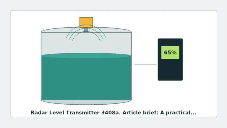
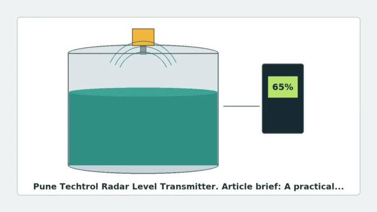
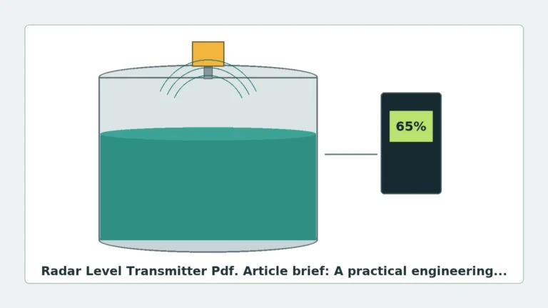
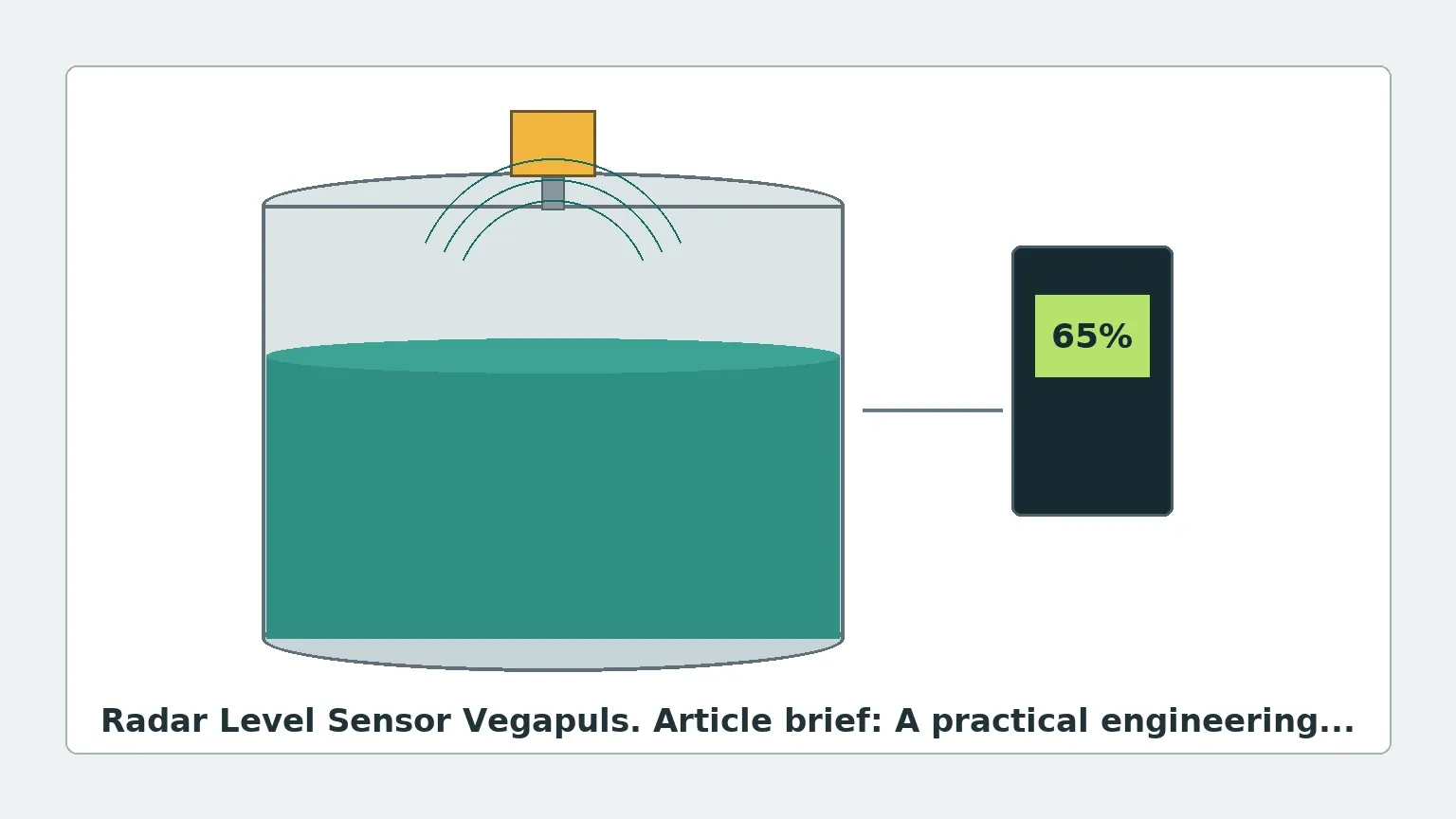
Radar level measurement is based on the "Time of Flight" (ToF) principle. The sensor, mounted at the top of a vessel, emits microwave signals toward the medium. These signals are reflected by the surface of the product and returned to the sensor. By measuring the time interval between emission and reception, the instrument calculates the distance to the surface and, subsequently, the level of the material in the tank.
Pulse Radar vs. FMCW
Modern radar sensors generally utilize one of two primary modulation techniques:
1. Pulse Radar: The sensor emits short microwave pulses and measures the time they take to travel to the surface and back. This method is energy-efficient and suitable for many standard applications.
2. Frequency Modulated Continuous Wave (FMCW): The sensor emits a continuous signal with a constantly changing frequency. The distance is determined by the frequency difference between the emitted and the received signal at any given moment. FMCW, particularly at high frequencies like 80 GHz, offers significantly higher resolution and signal-to-noise ratios, making it the preferred choice for complex geometries or turbulent surfaces.
The Role of Frequency
The frequency of the microwave signal (measured in GHz) determines the beam angle and the sensor’s ability to handle obstacles.
- 6 GHz to 10 GHz (C-Band): Better at penetrating foam and heavy steam but requires large antennas to maintain a narrow beam.
- 26 GHz (K-Band): A versatile frequency used in many standard Radar Level Meters. It balances antenna size with signal focus.
- 80 GHz (W-Band): The technology utilized in the latest radar level sensor vegapuls models. The high frequency allows for extremely narrow beam angles (as small as 3°), which is critical for avoiding internal tank obstructions like agitators or heating coils.
2. Technical Comparison and Selection Criteria
When selecting a radar sensor, engineers must match the instrument's capabilities to the physical properties of the medium and the vessel's environment. The following table outlines typical selection parameters based on common industrial configurations.
Table 1: Radar Level Sensor Selection Matrix
| Feature | 26 GHz Radar (Standard) | 80 GHz Radar (High Precision) | Guided Wave Radar (GWR) |
| :— | :— | :— | :— |
| Best Use Case | Large tanks, simple liquids | Small vessels, solids, narrow nozzles | Low dielectric liquids, bypass pipes |
| Beam Angle | 8° to 20° | 3° to 6° | N/A (Conducted along probe) |
| Measurement Range | Up to 30 meters | Up to 120 meters | Up to 75 meters |
| Accuracy | ±3 mm to ±5 mm | ±1 mm | ±2 mm |
| Foam Resistance | Moderate | Low (Signal may scatter) | High (Probe contacts liquid) |
| Dust Resistance | High | Excellent | Moderate |
| Dielectric Constant ($ε_r$) | Min 1.6 | Min 1.1 | Min 1.4 |
Dielectric Constant ($ε_r$)
The dielectric constant of the medium is the most critical factor in radar measurement. It determines how much energy is reflected back to the sensor. Water has a high $ε_r$ (~80) and is easy to measure. In contrast, hydrocarbons like oil or plastic pellets have low $ε_r$ values (1.4 to 2.5), requiring more sensitive electronics and higher-gain antennas to ensure a reliable return signal.
3. The Vegapuls Series: Application-Specific Solutions
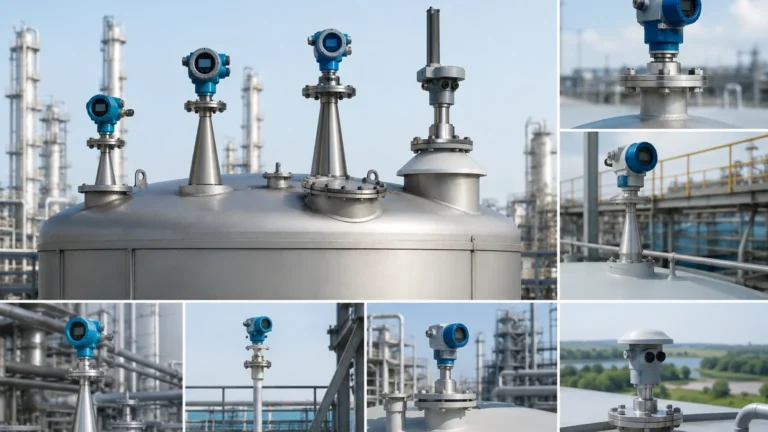
The radar level sensor vegapuls line is categorized to address specific industrial challenges. Understanding these categories helps in identifying the appropriate equivalent when sourcing Radar Level Meters for global projects.
* Vegapuls 61/62/63 (26 GHz): These are the workhorses for liquid applications. The 62 is often used for corrosive media due to its PTFE-encapsulated antenna, while the 63 is designed for hygienic applications in the food and pharmaceutical industries.
* Vegapuls 64 (80 GHz): Specifically designed for liquids in small tanks or vessels with many internals. Its narrow beam avoids false echoes from agitators.
* Vegapuls 67/68/69 (Solids): The 69 model, an 80 GHz sensor, is optimized for bulk solids like cement, grain, or ores. It can penetrate heavy dust and measure reliably even in tall, narrow silos where traditional ultrasonic sensors fail.
4. Installation Considerations and Constraints
Even the most advanced radar sensor will perform poorly if installed incorrectly. Engineering teams must adhere to strict geometric constraints during the design phase.
Nozzle Height and Diameter
The antenna must be able to "see" out of the mounting nozzle. If the nozzle is too long or the diameter too narrow, the radar signal will reflect off the nozzle walls, creating a "ringing" effect that masks the true level signal. For 80 GHz sensors, nozzle interference is minimized, but for 26 GHz models, the antenna should ideally extend slightly beyond the bottom of the nozzle.
The "Dead Zone" (Blocking Distance)
Every radar sensor has a minimum distance (dead zone) near the antenna where measurements are not possible. This typically ranges from 50 mm to 200 mm. If the tank is overfilled into this zone, the sensor may report an error or a fixed high-level value.
Avoiding Obstructions
The radar beam spreads as it travels. Engineers must calculate the beam diameter at the bottom of the tank using the following formula:
$$D = 2 × L × an(α/2)$$
* D: Beam diameter at distance L
* L: Distance from the sensor
* α: Beam angle of the sensor
If any internal structures (ladders, pipes, agitators) fall within this diameter, they will create false echoes. While modern software can "map out" these echoes, it is always better to position the sensor in a clear path to the product surface.
5. Limitations and Application Risks
While highly versatile, Radar Level Meters are not universal solutions. Certain conditions can impair performance:
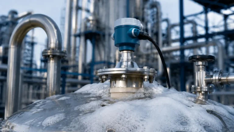
1. Heavy Foam: Dense, thick foam (like shaving cream) can absorb the radar signal entirely. In such cases, Guided Wave Radar (GWR) or hydrostatic pressure transmitters are often more reliable.
2. Turbulence: Rapidly moving surfaces scatter the signal. This can be mitigated by using software damping or installing the sensor inside a stilling well (a bypass pipe that stabilizes the liquid level).
3. Condensation and Buildup: While 80 GHz sensors like the radar level sensor vegapuls 64 are designed to ignore minor buildup, heavy coating on the antenna lens will eventually attenuate the signal. Air purging systems are recommended for extremely sticky or dusty environments.
6. Maintenance and Commissioning for International Buyers
For international procurement, ensuring that the equipment is "plug-and-play" is vital. Most modern radar sensors support digital protocols such as HART, Profibus PA, or Foundation Fieldbus, allowing for remote calibration via PC or handheld communicator.
Checklist for Buyers:
- Process Connection: Ensure the flange or thread standard (ANSI, DIN, JIS) matches the local piping.
- Certifications: Verify ATEX/IECEx for hazardous zones or FDA/3A for hygienic processes.
- Output Signal: Confirm if a 4-20mA analog signal or a digital bus communication is required.
- Housing Material: Choose plastic for light duty, aluminum for standard industrial use, or stainless steel (316L) for offshore or corrosive environments.
7. Frequently Asked Questions (FAQ)
Q: Can a radar level sensor measure through a plastic tank lid?
A: Yes. Since plastic is non-conductive, microwaves can pass through it. This allows for "non-invasive" measurement where the sensor is mounted outside a plastic IBC or storage tank.
Q: How does temperature affect radar measurement?
A: Unlike ultrasonic sensors, which depend on the speed of sound (which changes with air density/temperature), radar signals travel at the speed of light. Therefore, radar is virtually unaffected by temperature fluctuations or vacuum conditions.
Q: What is the difference between "Accuracy" and "Repeatability"?
A: Accuracy is how close the measurement is to the true value (e.g., ±1 mm). Repeatability is the sensor's ability to provide the same result under identical conditions. In process control, high repeatability is often more important than absolute accuracy.
Q: Is 80 GHz always better than 26 GHz?
A: Not necessarily. While 80 GHz offers better focus and smaller antennas, 26 GHz is often more cost-effective for large, simple storage tanks where high precision is not required.
Conclusion
The evolution of the radar level sensor vegapuls and similar high-frequency Radar Level Meters has simplified many previously impossible measurement tasks. By focusing on the dielectric properties of the medium, the geometry of the vessel, and the specific frequency requirements, engineers can implement level measurement solutions that require minimal maintenance and provide years of reliable data. Whether dealing with the extreme dust of a cement silo or the precise requirements of a pharmaceutical reactor, selecting the correct radar technology remains a cornerstone of modern industrial process design.