Radar Level Transmitter Atex
Radar Level Transmitter ATEX: Engineering Guide for Hazardous Areas
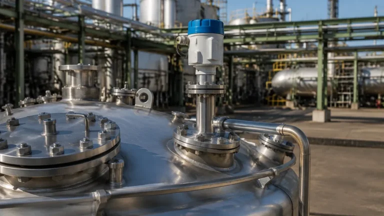
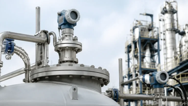
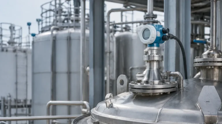
In industrial process automation, the requirement for precise, non-contact level measurement often intersects with the necessity for explosion protection. For engineers operating in the chemical, petrochemical, and oil and gas sectors, the radar level transmitter ATEX certified is a critical component for ensuring both operational efficiency and site safety.
This guide explores the technical principles, selection criteria, and installation requirements for radar level measurement in hazardous environments, providing a factual framework for selecting the appropriate instrumentation.
Understanding Radar Level Measurement Principles
Before selecting a specific instrument, it is essential to understand the underlying physics of radar technology. Radar level meters operate on the principle of electromagnetic wave propagation. Unlike ultrasonic sensors, which rely on sound waves and are affected by air temperature and pressure, radar waves travel at the speed of light and are largely independent of the vapor space atmosphere.
Time of Flight (ToF)
Most industrial radar transmitters utilize the Time of Flight (ToF) principle. The device emits a high-frequency signal from the antenna toward the product surface. The signal is reflected by the dielectric change at the surface and returned to the receiver. The distance ($D$) is calculated based on the time delay ($t$) and the speed of light ($c$):
$$D = \frac{c \times t}{2}$$
FMCW vs. Pulse Radar
There are two primary modulation techniques used in modern Radar Level Meters:
1. Pulse Radar: The transmitter sends out short microwave pulses and measures the time it takes for the pulse to return. This method is energy-efficient and suitable for many standard applications.
2. Frequency Modulated Continuous Wave (FMCW): The transmitter emits a continuous signal with a constantly changing frequency. The distance is determined by the frequency difference between the transmitted and received signals at any given moment. FMCW generally offers higher accuracy and better signal-to-noise ratios, especially in complex environments with internal tank obstructions.
The Role of ATEX Certification in Level Instrumentation
In the European Union and many international markets, equipment used in explosive atmospheres must comply with the ATEX directive (2014/34/EU). When a device is labeled as a radar level transmitter ATEX, it has undergone rigorous testing to ensure it will not become an ignition source.
ATEX Zones and Categories
Instruments are categorized based on the environment they are designed to inhabit:
* Zone 0 / Category 1G: Areas where an explosive atmosphere is present continuously or for long periods (e.g., inside a fuel storage tank).
* Zone 1 / Category 2G: Areas where an explosive atmosphere is likely to occur in normal operation.
* Zone 2 / Category 3G: Areas where an explosive atmosphere is not likely to occur, but if it does, it will only exist for a short time.
Protection Types
Common protection methods for radar transmitters include:
* Ex ia (Intrinsic Safety): Limits the energy available to a level below what is required to ignite a specific hazardous atmospheric mixture.
* Ex d (Flameproof/Explosion-proof): The enclosure is designed to withstand an internal explosion and prevent the flame from reaching the external atmosphere.
Frequency Selection: 26 GHz vs. 80 GHz
The operating frequency of a radar level transmitter significantly impacts its performance, particularly in hazardous areas where tank geometry may be restricted.
26 GHz Radar
Traditionally the industry standard, 26 GHz radar offers a balance between beamwidth and signal penetration. It is effective for larger vessels and is less sensitive to heavy steam or condensation than higher frequencies. However, it has a wider beam angle, which may lead to interference from internal tank structures like agitators or heating coils.
80 GHz Radar
Modern 80 GHz technology provides a much narrower beam angle (often as low as 3°). This allows the signal to avoid internal obstructions and permits installation in smaller nozzles. In an ATEX context, the higher precision of 80 GHz radar reduces the risk of "false echoes" in complex reactor vessels, which is vital for preventing overfill scenarios in volatile liquid storage.
Selection Criteria for ATEX-Rated Radar Transmitters
When specifying a radar level transmitter for a hazardous zone, engineers must evaluate several technical parameters beyond the ATEX rating itself.
1. Dielectric Constant ($ε_r$)
The reflectivity of the medium depends on its dielectric constant. Materials with a low $ε_r$ (such as liquefied gases or hydrocarbons) reflect less energy. For these applications, a high-sensitivity radar or a guided wave radar (GWR) may be required. For non-contact radar, a larger antenna or a higher frequency (80 GHz) can help capture weaker signals.
2. Process Temperature and Pressure
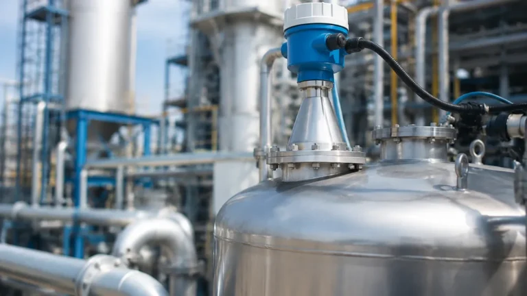
Standard radar sensors typically handle temperatures from -40°C to +150°C. For extreme applications, such as liquid nitrogen storage or high-pressure chemical reactors, specialized horn antennas with ceramic or PTFE seals are required to maintain the ATEX integrity of the vessel seal.
3. Material Compatibility
The wetted parts of the transmitter—usually the antenna and the process connection—must be chemically compatible with the medium. Common materials include 316L Stainless Steel, Hastelloy, and PTFE coatings.
Installation Guidelines for Explosive Atmospheres
Correct installation is paramount to ensuring the accuracy of a radar level transmitter ATEX and maintaining the safety rating of the facility.
Nozzle Considerations
The nozzle height and diameter should be chosen to prevent the radar beam from hitting the nozzle edge. For 80 GHz units, the nozzle can be longer and narrower compared to 26 GHz units. The antenna should ideally extend slightly beyond the nozzle bottom to prevent signal ringing within the pipe.
Obstruction Management
Avoid installing the radar directly over an inlet stream or near agitator blades. If an agitator is present, the transmitter should be mounted such that the beam is parallel to the shaft, and software-based "false echo suppression" should be used to map out the stationary reflections.
Grounding and Wiring
In hazardous areas, proper grounding of the instrument housing is mandatory to prevent static buildup. For intrinsically safe (Ex ia) installations, the use of an ATEX-certified zener barrier or galvanic isolator in the control room is required to limit the power sent to the field device.

Limitations and Process Challenges
While radar is a highly versatile technology, it is not without limitations:
* Heavy Foam: Dense, thick foam can absorb the radar signal, leading to signal loss. In such cases, a Guided Wave Radar (GWR) or a hydrostatic level transmitter might be more appropriate.
* Turbulence: Extreme surface turbulence can scatter the radar signal. While software filtering can mitigate this, it may increase the response time of the instrument.
* Dust and Build-up: In solids applications, significant dust can attenuate the signal. High-frequency radar with a lens antenna is often preferred here as the flat surface is less prone to material build-up.
Technical Comparison Table
| Feature | 26 GHz Radar | 80 GHz Radar | Guided Wave Radar (GWR) |
| :— | :— | :— | :— |
| Measurement Type | Non-contact | Non-contact | Contact (Probe) |
| Beam Angle | 8° – 15° | 3° – 6° | N/A (Signal follows probe) |
| Accuracy | ±3 mm | ±1 mm | ±2 mm |
| Max Range | Up to 30m | Up to 120m | Up to 75m |
| Suitability for Foam | Moderate | Poor | Good |
| ATEX Availability | Yes | Yes | Yes |
Maintenance and Safety Compliance
ATEX regulations require periodic inspection of equipment to ensure the protection mechanisms remain intact. For radar transmitters, this includes:
* Visual Inspection: Checking the enclosure for cracks and ensuring cable glands are tight and free from corrosion.
* Seal Integrity: For flameproof (Ex d) units, ensuring the flame path surfaces are not damaged.
* Calibration Verification: Periodic "dry runs" or comparison with manual dips to ensure the electronics haven't drifted, which is critical for SIL (Safety Integrity Level) rated loops.
Frequently Asked Questions (FAQs)
Q: Can I use a standard radar transmitter in an ATEX Zone 0?
A: No. Only equipment specifically certified for Category 1G (Zone 0) can be installed inside the tank where an explosive atmosphere is constantly present. Most ATEX radar transmitters are dual-rated, allowing the antenna to be in Zone 0 while the housing is in Zone 1.
Q: How does the dielectric constant affect the ATEX rating?
A: The dielectric constant doesn't change the ATEX rating, but it affects the reliability of the measurement. If the signal is lost due to a low dielectric constant, the safety system might trigger a fault, which could lead to unnecessary plant shutdowns.
Q: Is 80 GHz always better than 26 GHz for hazardous areas?
A: Not necessarily. While 80 GHz offers better precision and smaller footprints, 26 GHz is often more robust in the presence of heavy steam, condensation, or certain types of foam.
Q: Do I need a special cable for an ATEX radar transmitter?
A: Yes, typically shielded twisted pair cabling is required, and for intrinsically safe circuits, the cable must be clearly identified (often with a blue jacket) and meet specific capacitance and inductance limits.
Conclusion
Selecting a radar level transmitter ATEX involves a detailed analysis of the process environment, the physical properties of the medium, and the specific requirements of the hazardous zone. By understanding the differences between frequencies and protection types, engineers can implement a solution that provides accurate data while adhering to strict international safety standards. For complex applications, consulting with instrumentation specialists is recommended to ensure the chosen device meets all operational and regulatory boundaries.