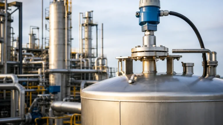
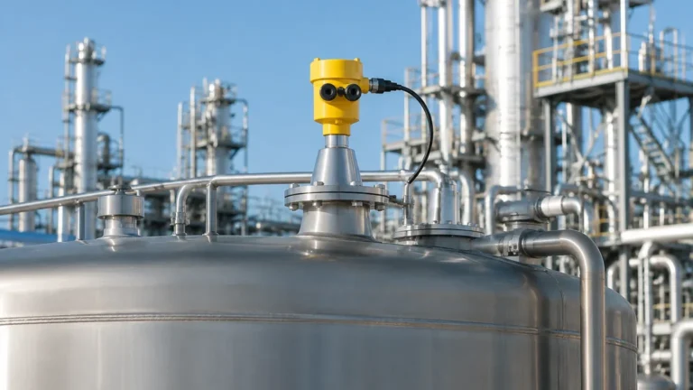
Radar Level Transmitter Animation
Radar Level Transmitter Animation: A Technical Guide to Visualizing Non-Contact Measurement
In the field of industrial automation, visualizing how a sensor interacts with its environment is crucial for both system design and troubleshooting. A radar level transmitter animation serves as more than just a marketing tool; it is a fundamental engineering resource that illustrates the complex physics of electromagnetic wave propagation, reflection, and signal processing. For engineers and procurement specialists, understanding these visual representations is the first step toward selecting the correct Radar Level Meters for challenging process environments.
Radar technology has evolved from simple pulse-echo systems to sophisticated Frequency Modulated Continuous Wave (FMCW) systems. This article provides a deep dive into the measurement principles, selection criteria, and practical installation constraints that define modern radar level instrumentation.
1. Measurement Principles: How Radar "Sees" the Level
To understand a radar level transmitter animation, one must first understand the two primary methods of microwave level measurement: Pulse Radar and FMCW Radar.
Pulse Radar (Time of Flight)
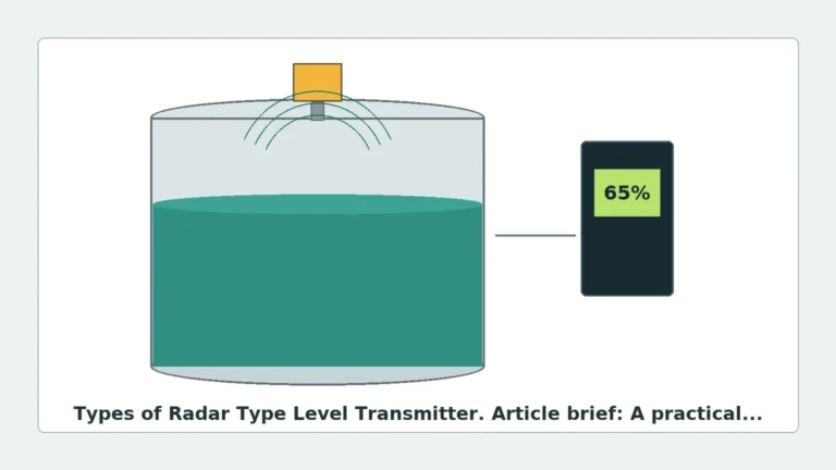
Pulse radar transmitters emit a high-frequency microwave pulse toward the product surface. The pulse travels at the speed of light, hits the surface, and reflects back to the antenna. The instrument measures the "Time of Flight" (ToF).
* The Formula: $D = (c \times t) / 2$, where $D$ is the distance, $c$ is the speed of light, and $t$ is the transit time.
* Visualization: In an animation, this is typically shown as a discrete packet of energy moving down and returning.
FMCW Radar (Frequency Shift)
Frequency Modulated Continuous Wave (FMCW) is the preferred technology for high-precision industrial applications. Instead of a single pulse, the transmitter emits a continuous signal with a constantly changing frequency (a frequency sweep).
When the reflected signal is received, it is compared to the signal being emitted at that exact moment. The difference in frequency ($Δf$) is directly proportional to the distance.
* Advantage: FMCW provides much higher resolution and a better signal-to-noise ratio than pulse radar, making it ideal for measuring liquids with low dielectric constants or in tanks with heavy agitation.
2. Interpreting the Radar Level Transmitter Animation and Echo Curve
In a B2B engineering context, the "animation" often refers to the real-time echo curve displayed on a technician's laptop or the device's HMI. This visual data is critical for commissioning.
The Echo Curve Components
1. The Launch Pulse: The initial peak representing the signal leaving the antenna.
2. The Measurement Echo: The peak representing the actual material level. The software identifies this peak to calculate the distance.
3. False Echoes: Reflections caused by internal tank obstructions like agitators, heating coils, or ladders.
4. The Noise Floor: The background electromagnetic interference that the transmitter must filter out.
Modern Radar Level Meters utilize algorithms to "mask" or "map" false echoes. An animation of this process shows the software creating a threshold line that ignores static obstructions, ensuring the transmitter only tracks the moving surface of the product.
3. Technical Selection: Frequency and Antenna Types
Choosing the right radar transmitter requires matching the frequency and antenna design to the specific application. The following table outlines the standard industry options:
| Feature | 6 GHz (C-Band) | 26 GHz (K-Band) | 80 GHz (W-Band) |
| :— | :— | :— | :— |
| Beam Angle | Wide (approx. 20°-30°) | Medium (approx. 8°-12°) | Narrow (approx. 3°-4°) |
| Accuracy | ±10 mm (0.39 in) | ±2-5 mm (0.08-0.2 in) | ±1 mm (0.04 in) |
| Best Use Case | Heavy foam, steam, or turbulence | General purpose liquids/solids | Small nozzles, tall silos, low dielectric liquids |
| Antenna Size | Large (Horn) | Medium (Horn/Lens) | Small (Lens/Flush) |
| Penetration | High (Good for steam) | Moderate | Low (Sensitive to buildup) |
Antenna Geometry
* Horn Antennas: Standard for most large-vessel liquid applications. They are robust and handle condensation well.
* Lens Antennas: Often used with high-frequency 80 GHz units. They allow for flush mounting and are easier to clean in hygienic (food/pharma) applications.
* Rod Antennas: Ideal for small openings or corrosive environments where the antenna must be encased in PTFE (Teflon).
4. Installation Considerations and Constraints
A radar level transmitter animation often highlights the "cone" of the radar beam. Proper installation ensures this cone does not intersect with the tank wall or internal structures.
Nozzle Height and Diameter
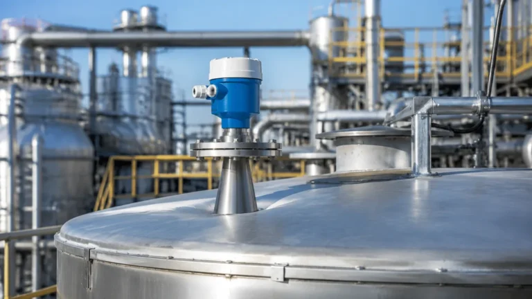
The antenna should ideally extend slightly past the bottom of the mounting nozzle. If the nozzle is too long or narrow, the radar signal will reflect off the nozzle walls (ringing), creating a large "dead zone" at the top of the tank. For 80 GHz transmitters, the narrow beam allows for much longer nozzles than 26 GHz units.
Positioning
* Avoid the Center: Never mount a radar transmitter in the exact center of a domed-roof tank. The dome acts as a parabolic reflector, concentrating false echoes back to the sensor.
* Distance from Wall: Maintain a minimum distance from the tank wall (typically 1/6th of the tank diameter) to prevent side-lobe reflections.
* Inflow Interference: Ensure the beam does not cross the path of the falling product during filling, as this will cause signal scattering and erratic readings.
Stillwells and Bypass Pipes
For liquids with heavy foam or extremely low dielectric constants (like liquid nitrogen or light hydrocarbons), mounting the radar inside a stillwell or bypass pipe is recommended. The pipe acts as a waveguide, concentrating the signal and eliminating surface turbulence.

5. Practical Limitations and Application Risks
While radar is one of the most versatile level measurement technologies, it is not infallible. Understanding these risks is essential for international buyers and plant engineers.
Dielectric Constant (εr)
The dielectric constant of the material determines how much energy is reflected.
* Water (εr ≈ 80): Excellent reflector.
* Oil/Hydrocarbons (εr ≈ 2): Poor reflectors.
If the dielectric constant is below 1.5, a standard non-contact radar may struggle. In these cases, a Guided Wave Radar (GWR) or a high-sensitivity 80 GHz FMCW unit is required.
Foam and Turbulence
Heavy, dense foam can absorb the radar signal entirely. While low-frequency (6 GHz) radar can sometimes penetrate thin foam, thick chemical foam often requires a different approach, such as a magnetic level gauge or a hydrostatic transmitter.
Dust and Condensation
In solid silos, heavy dust can attenuate high-frequency signals. Similarly, in liquid tanks, heavy condensation on the antenna lens can cause signal loss. Choosing a lens antenna with a "drip-off" design or utilizing an air purge system can mitigate these issues.
6. Maintenance and Troubleshooting
When a radar transmitter fails to provide an accurate reading, the first step is to review the echo curve (the live radar level transmitter animation).
* Signal Loss: If the measurement peak disappears, check for antenna coating or a change in the product's dielectric properties.
* Fixed Value Output: If the transmitter stays at one level despite changes in the tank, it is likely "locked" onto a false echo from an internal obstruction. Re-running the "false echo suppression" or "background mapping" routine usually resolves this.
* Jumpiness: This is often caused by surface agitation. Increasing the damping (smoothing) factor in the software settings can stabilize the output.
7. Frequently Asked Questions (FAQ)
Q: Can radar level transmitters measure through plastic tank walls?
A: Yes, because plastic has a low dielectric constant, microwaves can pass through it. This allows for non-intrusive measurement where the sensor is mounted outside a plastic IBC or storage tank.
Q: Is 80 GHz always better than 26 GHz?
A: Not necessarily. While 80 GHz offers better precision and smaller antennas, 26 GHz is often more cost-effective and more tolerant of heavy steam or condensation in large-scale industrial tanks.
Q: How does temperature and pressure affect radar?
A: Unlike ultrasonic sensors, radar is largely unaffected by changes in air temperature, pressure, or vacuum because electromagnetic waves do not require a medium to travel. However, the physical housing and seals of the transmitter must be rated for the process conditions (e.g., up to 200°C or 40 Bar).
Q: What is the difference between 2-wire and 4-wire radar?
A: 2-wire transmitters are loop-powered (the same two wires carry the 4-20mA signal and the power), making them easier to install. 4-wire transmitters have separate power and signal lines, which is often necessary for high-power units or those with integrated heating elements.
Conclusion
Understanding the mechanics behind a radar level transmitter animation allows engineers to move beyond basic product descriptions and into the realm of application-specific engineering. By considering frequency, antenna design, and the physical constraints of the vessel, users can ensure long-term reliability and accuracy. For those seeking high-performance instrumentation, exploring the range of Radar Level Meters provides the technical foundation needed for modern industrial automation.
When selecting a device, always confirm the dielectric constant of your media and the internal geometry of your tank with the manufacturer to ensure the chosen technology aligns with your operational goals.