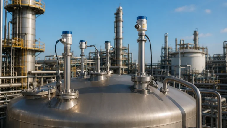
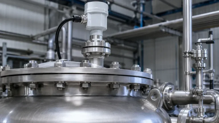
Radar Level Transmitter Calculation
Radar Level Transmitter Calculation: A Comprehensive Engineering Guide
In the field of industrial automation, accurate level measurement is critical for process safety, inventory management, and operational efficiency. Among the various technologies available, radar level measurement has emerged as a preferred solution due to its non-contact nature and reliability in harsh environments. However, achieving high precision requires more than just installing a device; it necessitates a thorough understanding of the underlying physics and the specific radar level transmitter calculation methods used to interpret microwave signals.
This guide provides a technical overview of how radar level transmitters operate, the mathematical formulas used for distance and level determination, and the practical considerations engineers must address during selection and installation.
Measurement Principles of Radar Technology
Radar level transmitters utilize electromagnetic waves, typically in the microwave frequency range (6 GHz to 80 GHz), to detect the surface of a material. Unlike ultrasonic sensors, which rely on sound waves and are affected by air temperature and pressure, radar waves travel at the speed of light and are largely unaffected by the vapor space composition.
There are two primary methods used in industrial radar level measurement:
1. Pulse Radar (Time of Flight)
Pulse radar transmitters emit a short microwave pulse toward the product surface. The signal reflects off the surface and returns to the sensor. The transmitter measures the time elapsed between transmission and reception.
2. Frequency Modulated Continuous Wave (FMCW)
FMCW radar transmits a continuous signal with a constantly changing frequency. When the reflected signal is received, it is compared to the signal being transmitted at that exact moment. The difference in frequency (the "beat frequency") is directly proportional to the distance the signal has traveled. FMCW is generally more accurate than pulse radar and is the standard for modern high-frequency 80 GHz Radar Level Meters.
Fundamental Radar Level Transmitter Calculation
To convert a microwave reflection into a usable level reading, the transmitter's internal processor performs a series of calculations. Understanding these formulas helps engineers troubleshoot signal issues and configure the device correctly.
The Distance Formula
The core of any radar level transmitter calculation is the relationship between the speed of light, time, and distance. The basic formula for distance ($D$) is:
$$D = \frac{c \times t}{2}$$
Where:
* $D$: The distance from the sensor reference point to the material surface (meters).
* $c$: The speed of light in the medium (approximately $3 \times 10^8$ m/s in a vacuum or air).
* $t$: The measured transit time (seconds).
The result is divided by two because the signal travels to the surface and back.
Level and Volume Calculation
Once the distance ($D$) is known, the actual level ($L$) of the material is calculated relative to the tank height ($H$):
$$L = H – D$$
Where:
* $L$: The height of the material (level).
* $H$: The total height of the vessel (from the zero point/bottom to the sensor reference point).
If the objective is to calculate volume ($V$), the transmitter applies the level measurement to a strapping table or a geometric formula based on the tank shape (e.g., vertical cylinder, horizontal cylinder with dished ends, or sphere).
The Role of Dielectric Constant ($ε_r$)
The dielectric constant of the material being measured is the most significant factor in signal reflection. A portion of the radar energy is reflected at the surface, while the rest penetrates the medium.
* High $ε_r$ (e.g., Water, $ε_r ≈ 80$): Reflects a very strong signal.
* Low $ε_r$ (e.g., Hydrocarbons, $ε_r ≈ 1.9 – 4$): Reflects a weak signal, requiring high-sensitivity electronics or Guided Wave Radar (GWR).
If the dielectric constant is too low (typically below 1.4), the radar signal may pass through the material entirely and reflect off the bottom of the tank, leading to false readings.
Selection Criteria for Industrial Applications
Choosing the right radar frequency and technology depends on the physical properties of the medium and the vessel geometry. The following table compares the most common radar technologies used in industrial settings.
Technical Comparison Table
| Feature | 26 GHz Pulse Radar | 80 GHz FMCW Radar | Guided Wave Radar (GWR) |
| :— | :— | :— | :— |
| Measurement Type | Non-contact | Non-contact | Contact (Probe-based) |
| Accuracy | ±3 mm | ±1 mm | ±2 mm |
| Max Range | 30 – 70 meters | Up to 120 meters | Up to 30 meters |
| Beam Angle | 8° to 20° | 3° to 8° | N/A |
| Obstruction Handling | Moderate | Excellent (Narrow Beam) | Excellent (Ignores foam) |
| Best Use Case | Large tanks, liquids | Narrow tanks, solids, dust | Low dielectric, foam, interface |
Installation Considerations and Constraints
Even with a precise radar level transmitter calculation, poor installation can lead to measurement errors. Engineers must consider the following factors:
1. The Beam Angle and False Echoes
The radar signal spreads as it travels. The "beam angle" defines the area where the signal energy is concentrated. If the beam hits internal obstructions like ladders, agitators, or heating coils, it creates "false echoes."
Modern Radar Level Meters utilize software-based "echo mapping" to record these static reflections and ignore them during the level calculation process. However, it is always better to install the sensor at least 200mm to 500mm away from the tank wall to avoid interference.
2. Nozzle Height and Diameter
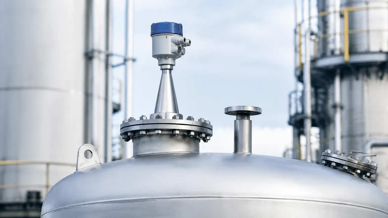
The mounting nozzle can interfere with the signal if it is too long or too narrow. For 26 GHz radars, the antenna should ideally extend slightly beyond the nozzle. For 80 GHz radars, the narrow beam allows for installation in taller nozzles, but the nozzle interior must be smooth to prevent signal scattering.
3. The Dead Zone (Blocking Distance)
Every radar transmitter has a "dead zone" directly beneath the antenna (typically 50mm to 200mm). In this zone, the device cannot process the return signal because the transmission is still occurring. The radar level transmitter calculation for maximum level must account for this to prevent overfilling.
Limitations and Application Risks
While radar is highly versatile, certain conditions can degrade performance:
* Heavy Foam: Dense, thick foam can absorb the microwave signal, preventing a return echo. In such cases, Guided Wave Radar or a lower frequency radar (which penetrates foam better) may be required.
* Extreme Turbulence: Rapidly moving surfaces can scatter the signal. This is often mitigated by using a stilling well or increasing the damping/averaging time in the transmitter settings.
* Dust and Condensation: While 80 GHz radar handles dust well, heavy buildup on the antenna lens can attenuate the signal. Many high-end transmitters include an air purge connection to keep the lens clean.
Frequently Asked Questions (FAQ)
Q: How does temperature affect the radar level transmitter calculation?
A: Unlike ultrasonic sensors, electromagnetic waves are not significantly affected by air temperature. Radar is suitable for extreme temperatures, from cryogenic applications to molten glass, provided the sensor housing and seal are rated for the process.
Q: Can radar measure the interface between two liquids?
A: Yes, Guided Wave Radar (GWR) is typically used for interface measurement (e.g., oil over water). The signal reflects off the top layer and a portion continues through to reflect off the interface of the second liquid.
Q: Is 80 GHz always better than 26 GHz?
A: Not necessarily. While 80 GHz offers a narrower beam and better accuracy, 26 GHz may be more cost-effective for simple, large-scale storage tanks where high precision is not required and obstructions are minimal.
Q: What is the minimum dielectric constant required for radar?
A: Most modern non-contact radars can measure materials with a dielectric constant ($ε_r$) as low as 1.4. For materials below this, such as liquid nitrogen or certain liquefied gases, specialized GWR or coaxial probes are recommended.
Conclusion
Accurate industrial level measurement relies on the precise execution of the radar level transmitter calculation. By understanding the relationship between frequency, dielectric properties, and vessel geometry, engineers can select the most appropriate instrumentation for their specific needs. Whether managing volatile chemicals or bulk solids, the integration of advanced Radar Level Meters ensures long-term reliability and safety in process control.
When specifying a system, always confirm the process temperature, pressure, chemical compatibility of the wetted parts, and the dielectric constant of the medium to ensure the transmitter's calculation algorithms can provide the necessary accuracy.