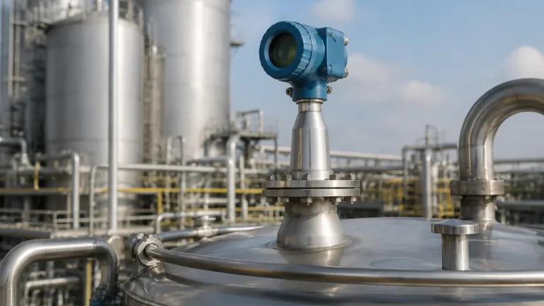
Radar Level Sensor Keyence
Radar Level Sensor Keyence: An Engineering Guide to High-Frequency Level Measurement
In the landscape of industrial automation, the demand for non-contact, high-precision level measurement has led to significant advancements in radar technology. Among the various solutions available to process engineers, the radar level sensor keyence—specifically the FR Series—has gained attention for its ability to handle complex environments using high-frequency signals. This guide explores the engineering principles behind high-frequency radar, compares selection criteria, and provides practical installation advice for integrating Radar Level Meters into industrial workflows.
Understanding Radar Level Measurement Principles
Radar level measurement operates on the principle of reflecting electromagnetic waves off the surface of a medium. Unlike ultrasonic sensors, which rely on sound waves and are affected by air temperature, pressure, and gas composition, radar waves travel at the speed of light and are largely immune to environmental variations. There are two primary methods used in industrial radar sensors: Time of Flight (ToF) and Frequency Modulated Continuous Wave (FMCW).
Time of Flight (Pulse Radar)
Pulse radar sensors emit a short microwave pulse toward the product surface. The sensor measures the time it takes for the pulse to travel to the surface and back. Since the speed of light is constant, the distance is calculated as:
Distance = (Speed of Light × Time of Flight) / 2
Frequency Modulated Continuous Wave (FMCW)
FMCW radar, which is the technology often utilized in a high-performance radar level sensor keyence, emits a continuous signal with a constantly changing frequency. When the reflected signal is received, it is compared to the signal being emitted at that exact moment. The frequency difference is directly proportional to the distance. FMCW is generally preferred for its higher accuracy and better signal-to-noise ratio in challenging conditions.
The Evolution of High-Frequency Radar (80GHz)
Traditional radar sensors often operated in the 6GHz or 26GHz range. However, the industry has shifted toward 80GHz technology. This higher frequency allows for a much narrower beam angle, which is critical for avoiding internal tank obstructions like agitators, ladders, or heating coils.
For instance, a 26GHz sensor might have a beam angle of 10° to 15°, requiring a large clearance zone. In contrast, an 80GHz radar level sensor keyence can achieve beam angles as narrow as 3°, allowing it to be installed in tall, narrow nozzles or tanks with complex internal geometries. This precision reduces the risk of "false echoes"—reflections from the tank walls or internal hardware that can confuse the sensor.
Technical Specifications and Selection Criteria
When selecting between various Radar Level Meters, engineers must evaluate the physical properties of the medium and the vessel's environment. The following table provides a comparison of typical radar specifications found in industrial applications.
| Feature | 26GHz Pulse Radar | 80GHz FMCW Radar (Keyence FR Style) |
| :— | :— | :— |
| Beam Angle | 10° – 20° | 3° – 8° |
| Measurement Range | Up to 30m | Up to 120m |
| Accuracy | ±3 mm to ±5 mm | ±1 mm |
| Suitability for Foam | Moderate | High (with signal processing) |
| Nozzle Compatibility | Requires wide nozzles | Compatible with narrow/long nozzles |
| Dielectric Constant (εr) | > 1.9 | > 1.1 |
Dielectric Constant (εr) Considerations
The dielectric constant of the material being measured is the most critical factor in radar performance. Materials with high dielectric constants (e.g., water, εr ≈ 80) reflect signals strongly. Materials with low dielectric constants (e.g., plastic pellets or oils, εr < 2) reflect very little energy, making them harder to detect. High-frequency sensors are generally more sensitive and better equipped to handle these low-reflectivity materials.
Installation Guidelines for Optimal Performance
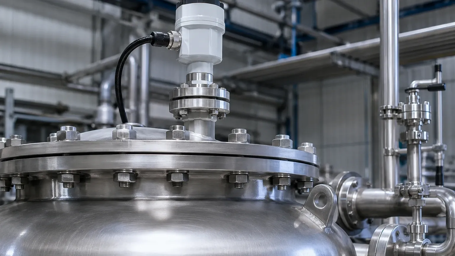
Proper installation is the difference between a reliable instrument and a constant source of maintenance alarms. When installing a radar level sensor keyence or similar high-frequency device, follow these engineering constraints:
1. Nozzle Height and Diameter: Ensure the antenna extends slightly below the bottom of the mounting nozzle to prevent signal interference from the nozzle edge. For 80GHz sensors, the narrow beam allows for longer nozzles, but the "dead zone" (blocking distance) near the antenna must still be respected.
2. Avoid the Center: Do not mount the sensor in the exact center of a domed tank. This can cause multiple reflections to converge at the sensor, leading to signal amplification errors.
3. Obstruction Clearance: Even with a narrow beam, it is best practice to maintain a clearance of at least 200 mm from the tank wall and keep the beam path clear of agitator blades or fill streams.
4. Alignment: The sensor should be mounted perpendicular to the liquid surface. In solid applications (silos), an alignment flange may be required to point the beam at the angle of repose of the material.
Limitations and Application Risks
While radar is highly versatile, it is not a universal solution. Engineers should be aware of the following limitations:
* Heavy Foam: While 80GHz radar can penetrate light foam, extremely dense, thick foam (like shaving cream) can absorb the radar signal entirely, leading to a loss of signal. In these cases, a guided wave radar or a magnetic level gauge may be more appropriate.
* Condensation and Buildup: Significant moisture buildup on the antenna lens can attenuate the signal. Many modern Radar Level Meters feature PTFE or PEEK lens covers that are flush-mounted to shed droplets, but heavy crystalline buildup will still require periodic cleaning.
* Vessel Geometry: In very small horizontal tanks, the radar signal may reflect off the bottom of the tank when the level is low. This requires "bottom echo suppression" software settings to ensure the sensor does not report a false level when the tank is empty.
Frequently Asked Questions (FAQ)
Q: Can a radar level sensor keyence measure through a plastic tank lid?
A: Yes. Because radar waves can penetrate non-conductive materials, it is possible to measure the level inside a plastic or fiberglass tank without cutting a hole in the vessel, provided the material thickness does not cause excessive signal attenuation.
Q: What is the difference between "Dead Zone" and "Accuracy Range"?
A: The dead zone (or blocking distance) is the area immediately below the sensor where measurement is impossible (typically 0 mm to 300 mm depending on the model). The accuracy range is the distance over which the sensor meets its stated tolerance (e.g., ±1 mm).
Q: How does dust affect 80GHz radar in powder applications?
A: High-frequency radar is excellent for dusty environments. Unlike ultrasonic sensors, which are blocked by airborne dust, radar waves pass through dust clouds with minimal loss, making them ideal for cement, flour, or plastic resin silos.
Q: Is 4-20mA or IO-Link better for radar sensors?
A: For traditional PLC integration, 4-20mA with HART is standard. However, for Industry 4.0 applications, IO-Link provides more diagnostic data, such as signal strength and internal temperature, which is highly useful for predictive maintenance.
Conclusion
The integration of a radar level sensor keyence into an industrial process offers significant advantages in terms of precision and reliability, particularly in narrow vessels or environments with steam and dust. By understanding the shift toward 80GHz technology and adhering to strict installation standards, facilities can achieve maintenance-free level monitoring. For a broader range of industrial applications, exploring various Radar Level Meters ensures that the selected technology matches the specific dielectric and atmospheric requirements of the process.