Radar Level Transmitter Connection
Radar Level Transmitter Connection: A Technical Engineering Guide
In the landscape of industrial process automation, the accuracy of level measurement is fundamental to operational safety, inventory management, and process efficiency. Among the various technologies available, Radar Level Meters have emerged as the preferred solution for challenging environments involving extreme temperatures, high pressures, and varying vapor compositions. However, the performance of these instruments is heavily dependent on the physical and electrical integration into the system. Understanding the nuances of a radar level transmitter connection—ranging from mechanical mounting interfaces to signal communication protocols—is essential for any instrumentation engineer or procurement specialist.
This guide provides a comprehensive technical overview of radar level transmitter connections, covering measurement principles, mechanical standards, electrical configurations, and critical installation constraints.
1. Measurement Principles and Connection Dynamics
Before selecting a specific radar level transmitter connection, it is vital to understand how the instrument interacts with the process medium. Radar level transmitters generally operate on one of two principles: Pulse Radar or Frequency Modulated Continuous Wave (FMCW).
Pulse Radar
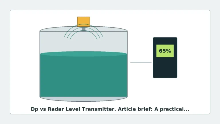
Pulse radar sensors emit high-frequency microwave pulses toward the material surface. The instrument measures the "time of flight" (ToF)—the duration it takes for the pulse to travel to the surface and return to the sensor. Because the speed of light is constant, the distance is easily calculated. This method is energy-efficient and suitable for many standard liquid applications.
FMCW Radar
FMCW (Frequency Modulated Continuous Wave) transmitters emit a continuous signal with a constantly changing frequency. The reflection from the product surface is compared to the emitted signal. The frequency difference between the transmitted and received signals is proportional to the distance. FMCW technology, particularly at higher frequencies like 80GHz, offers superior resolution and signal-to-noise ratios, making it ideal for solids, powders, and low-dielectric liquids.
The Role of the Connection
The physical connection serves as the gateway for these electromagnetic waves. The size and type of the connection determine the antenna geometry, which in turn dictates the beam angle. A narrower beam angle, often achieved with larger connections or higher frequencies, minimizes interference from tank walls and internal obstructions like agitators or heating coils.
2. Mechanical Connection Types
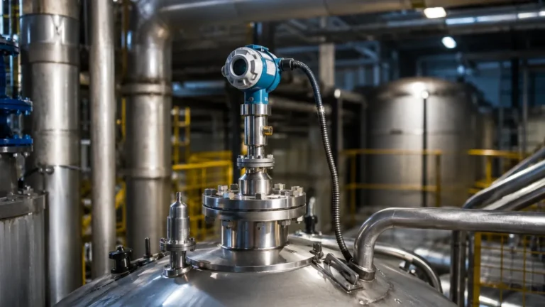
The mechanical radar level transmitter connection is the primary interface between the instrument and the vessel. Selecting the wrong connection can lead to leaks, signal attenuation, or mechanical failure.
Threaded Connections
Threaded connections are common in smaller vessels, bypass pipes, and open-channel applications. They are typically available in NPT (National Pipe Thread) or G (ISO 228-1) standards.
- Common Sizes: 1.5" (DN40) to 2" (DN50).
- Pros: Cost-effective, easy to install in compact spaces.
- Cons: Limited pressure ratings (typically up to 40 bar / 580 PSI) and potential for leaks if not properly sealed with PTFE tape or specialized compounds.
Flange Connections
Flanges are the industry standard for high-pressure and high-temperature industrial applications. They provide a robust, leak-proof seal and are easier to align than threaded connections.
- Standards: ANSI/ASME B16.5 (North America), DIN/EN 1092-1 (Europe), and JIS (Japan).
- Materials: Stainless steel 316L is standard, but specialized alloys like Hastelloy or PTFE-lined flanges are used for highly corrosive media.
- Pros: High pressure tolerance (up to 160 bar / 2320 PSI or higher), suitable for volatile chemicals.
Sanitary Connections
In the food, beverage, and pharmaceutical industries, the radar level transmitter connection must prevent bacterial growth and allow for Clean-in-Place (CIP) or Steam-in-Place (SIP) procedures.
- Types: Tri-Clamp, Varivent, or DIN 11851.
- Features: Gap-free designs and polished surfaces (Ra < 0.8 µm) to ensure no product residue remains trapped.
3. Electrical and Communication Connections
The electrical radar level transmitter connection facilitates power supply and data transmission. Modern industrial plants require seamless integration into Distributed Control Systems (DCS) or Programmable Logic Controllers (PLC).
2-Wire vs. 4-Wire Configurations
- 2-Wire (Loop Powered): The transmitter receives power and transmits the 4-20mA signal over the same pair of wires. This is the most common configuration in modern plants due to reduced wiring costs.
- 4-Wire: Power (usually 24V DC or 110/230V AC) and the signal output are separated. 4-wire systems are often required for high-power FMCW units or when integrated heaters/displays are used.
Communication Protocols
- 4-20mA HART: The global standard. It overlays a digital signal on the analog current loop, allowing for remote configuration and diagnostics.
- RS485 Modbus: Frequently used in oil and gas tank farms for multi-drop configurations, allowing many sensors to be connected to a single gateway.
- Profibus PA / Foundation Fieldbus: Used in complex plant architectures to provide high-speed digital communication and extensive device metadata.
4. Engineering Selection Table
When specifying a radar level transmitter connection, use the following table as a baseline for engineering requirements:
| Application Type | Recommended Connection | Pressure Range | Temperature Range | Signal Output |
| :— | :— | :— | :— | :— |
| Water Storage | 1.5" G/NPT Thread | < 3 bar (43 PSI) | -40°C to 80°C | 4-20mA/HART |
| Chemical Reactor | 3" ANSI 150# Flange | < 20 bar (290 PSI) | -40°C to 150°C | 4-20mA/HART |
| High-Pressure Gas | 4" ANSI 600# Flange | < 100 bar (1450 PSI) | -50°C to 250°C | Modbus/HART |
| Food Processing | 2" Tri-Clamp | < 10 bar (145 PSI) | -20°C to 130°C | 4-20mA/HART |
| Solid Silos | 4"-10" Gimbal Flange | Atmospheric | -40°C to 200°C | 4-20mA/HART |

5. Installation Considerations and Constraints
The physical placement of the radar level transmitter connection is as important as the connection type itself. Incorrect mounting is the leading cause of "false echoes" and signal loss.
Nozzle Geometry
The nozzle is the pipe extension on which the transmitter is mounted.
- Nozzle Height: The antenna (horn) should ideally extend beyond the nozzle bottom into the vessel. If the antenna remains inside a long, narrow nozzle, the radar waves will reflect off the nozzle walls, creating a large "dead zone" at the top of the tank.
- Nozzle Diameter: For 26GHz radar, a minimum nozzle diameter of 50mm (2") is usually required. For 80GHz radar, connections as small as 20mm (3/4") are possible due to the shorter wavelength.
Vessel Placement
- The 1/6 Rule: For cylindrical tanks, the radar level transmitter connection should ideally be placed at 1/6 of the tank diameter from the side wall. This avoids the center of the tank (where multiple reflections can converge) and the wall (where signal attenuation occurs).
- Internal Obstructions: Avoid mounting the connection directly above ladders, agitators, or inflow streams. If an obstruction is unavoidable, many modern Radar Level Meters offer "False Echo Suppression" software to map out and ignore these static reflections.
Beam Angle
The beam angle is determined by the frequency and the antenna size. A 3" (DN80) horn antenna at 26GHz might have a beam angle of 10°, while an 80GHz sensor with the same connection size might have a beam angle as narrow as 3°. A narrower beam requires less clearance from internal structures.
6. Limitations and Application Risks
While radar technology is versatile, certain conditions can compromise the radar level transmitter connection and overall performance:
1. Low Dielectric Constants (εr): Materials with very low dielectric constants (e.g., liquid nitrogen or certain dry powders) reflect very little radar energy. In these cases, a guided wave radar or a high-sensitivity FMCW transmitter with a large flange connection is required.
2. Heavy Foam: Dense, thick foam can absorb radar signals entirely. If the process involves significant foaming, engineers should consider a stilling well or a low-frequency radar that can penetrate the foam layer.
3. Condensation and Buildup: In high-humidity environments, water droplets can form on the antenna face. Selecting a connection that supports a PTFE "drop" antenna or an integrated air purge system can mitigate signal loss due to buildup.
7. Frequently Asked Questions (FAQ)
Q: Can I use a threaded radar transmitter on a flanged tank?
A: Yes, by using a thread-to-flange adapter. However, ensure the adapter material is compatible with the process medium and that the resulting nozzle height does not interfere with the radar beam.
Q: What is the "Dead Zone" in radar level measurement?
A: The dead zone (or blocking distance) is the area immediately below the sensor where it cannot accurately measure. This is typically between 50mm and 500mm depending on the frequency and antenna type. The radar level transmitter connection should be designed to keep the maximum product level below this zone.
Q: Does the material of the connection matter?
A: Absolutely. For corrosive liquids like hydrochloric acid, a standard stainless steel connection will fail. In such cases, a PVDF or PTFE-lined flange connection is mandatory to protect the instrument and the vessel integrity.
Q: How do I ground a radar level transmitter?
A: The transmitter should be grounded via the internal or external grounding terminal. In many cases, the metal mechanical connection (flange) provides an auxiliary ground to the tank, but a dedicated copper wire to the plant's common ground is recommended to prevent EMI (Electromagnetic Interference).
Conclusion
Selecting the appropriate radar level transmitter connection is a multi-disciplinary task that requires balancing mechanical robustness, chemical compatibility, and electromagnetic physics. By adhering to standard flange or thread specifications, accounting for nozzle geometry, and ensuring the electrical interface matches the plant's control architecture, engineers can ensure long-term reliability. For high-precision applications, 80GHz Radar Level Meters offer the greatest flexibility in connection sizing, allowing for accurate measurement even through small-diameter nozzles and in cluttered vessels.