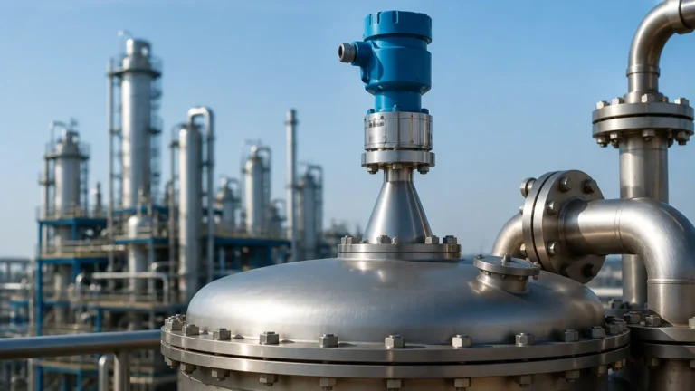
Radar Level Transmitter Working
Radar Level Transmitter Working: A Comprehensive Engineering Guide
In the landscape of industrial automation, precise level measurement is a cornerstone of operational efficiency, safety, and inventory management. Among the various technologies available, radar-based systems have emerged as the gold standard for challenging environments. Understanding the nuances of radar level transmitter working principles is essential for instrumentation engineers and procurement specialists who must select equipment that balances cost-effectiveness with high-performance reliability.
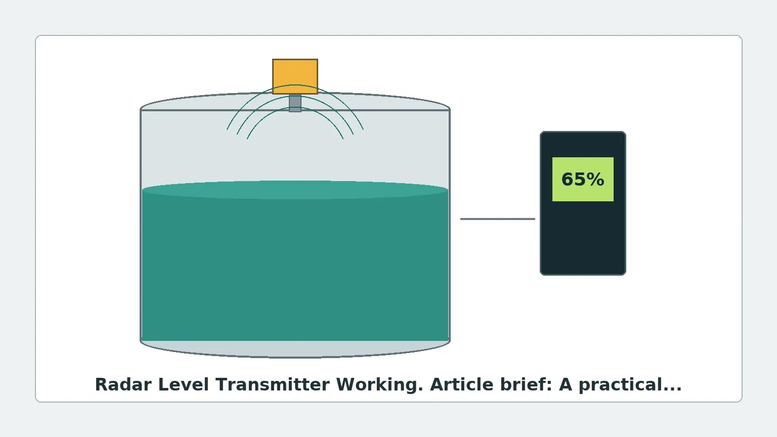
Radar Level Meters utilize electromagnetic waves to determine the distance to a liquid or solid surface. Unlike ultrasonic sensors, which rely on sound waves and are susceptible to air temperature and pressure fluctuations, radar signals travel at the speed of light and remain largely unaffected by the vapor space composition. This guide explores the technical mechanics, selection criteria, and installation requirements for modern radar level transmitters.
Fundamental Measurement Principles
To grasp how a radar level transmitter works, one must first distinguish between the two primary methods of signal modulation: Pulse Radar and Frequency Modulated Continuous Wave (FMCW).
1. Pulse Radar (Time-of-Flight)
Pulse radar transmitters emit a short microwave signal toward the target material. The signal reflects off the surface and returns to the sensor. The instrument measures the "Time of Flight" (ToF)—the interval between transmission and reception. Since the speed of electromagnetic waves is constant (approximately 300,000 km/s), the distance is calculated using the formula:
Distance = (Speed of Light × Time of Flight) / 2
Pulse radar is often favored in battery-powered or loop-powered applications due to its lower power consumption, though it may offer slightly lower precision in extremely turbulent conditions compared to FMCW.
2. Frequency Modulated Continuous Wave (FMCW)
FMCW is the preferred technology for high-precision industrial applications. Instead of a single pulse, the transmitter sends a continuous signal with a constantly changing frequency (a frequency sweep). When the reflected signal is received, it is compared to the signal being transmitted at that exact moment.
The frequency difference between the transmitted and received signals is directly proportional to the distance. This method allows for much higher resolution and better signal-to-noise ratios, making it ideal for measuring low-dielectric liquids or materials in tanks with internal obstructions.
The Mechanics of Radar Level Transmitter Working
The internal process of a radar level transmitter involves several critical stages that ensure the raw microwave reflection is converted into a reliable 4-20mA, HART, or Modbus signal.
Signal Emission and Beam Angle
The transmitter’s electronics generate a high-frequency signal (typically ranging from 6GHz to 80GHz) which is directed by an antenna. The antenna design determines the "beam angle." A narrower beam angle is generally desirable as it focuses energy on the product surface and minimizes false reflections from tank walls, agitators, or ladders.
Reflection and the Dielectric Constant (εr)
The success of the radar level transmitter working depends heavily on the dielectric constant of the medium being measured. The dielectric constant is a measure of a material's ability to reflect electromagnetic energy.
- High Dielectric (εr > 10): Materials like water or aqueous solutions reflect signals very strongly, making them easy to measure.
- Low Dielectric (εr < 2): Materials like hydrocarbons, oils, or plastic pellets absorb more energy and reflect less. In these cases, high-sensitivity FMCW radar or Guided Wave Radar (GWR) is often required.
Signal Processing and Echo Mapping
Modern transmitters use advanced algorithms to perform "echo mapping." The device records all reflections within the tank—including those from fixed obstructions—and creates a "map" of the empty vessel. These static echoes are then filtered out, allowing the transmitter to track only the dynamic level of the product.
Contact vs. Non-Contact Radar
When selecting Radar Level Meters, engineers must choose between non-contact and contact (Guided Wave) designs.
| Feature | Non-Contact Radar | Guided Wave Radar (GWR) |
| :— | :— | :— |
| Measurement Type | Top-down, no contact with media | Signal travels along a probe/cable |
| Best For | Corrosive liquids, hygienic applications | Low dielectric fluids, foam, turbulence |
| Installation | Mounted on top nozzle | Probe must reach the tank bottom |
| Maintenance | Minimal (no moving parts/contact) | Potential for buildup on the probe |
| Pressure/Temp | High tolerance | High tolerance |
Frequency Selection: 26GHz vs. 80GHz
The frequency of the radar signal significantly impacts performance.
* 26GHz Radar: A versatile mid-range frequency suitable for most liquid applications. It handles steam and some dust better than lower frequencies but has a wider beam angle than 80GHz models.
* 80GHz Radar: The current industry standard for precision. Because of the shorter wavelength, 80GHz transmitters can use smaller antennas while achieving a very narrow beam angle (often as low as 3 degrees). This allows for measurement in tall, narrow silos or tanks with complex internal structures without interference.
Engineering Selection Table
| Application | Recommended Technology | Key Reason |
| :— | :— | :— |
| Water Treatment Tanks | 80GHz Non-contact | High accuracy, easy installation over open basins. |
| Chemical Storage (Corrosive) | PTFE-lined Non-contact | Protects instrument from aggressive vapors. |
| Oil/Hydrocarbon Separators | Guided Wave Radar (GWR) | Reliability with low dielectric and interface layers. |
| Cement/Grain Silos | 80GHz High-Power Radar | Penetrates heavy dust and measures uneven surfaces. |
| Small Process Vessels | 80GHz Non-contact | Narrow beam avoids nozzle interference and agitators. |
Installation Considerations and Constraints
Even the most advanced radar transmitter will fail if installed incorrectly. To ensure the radar level transmitter working remains accurate, follow these engineering guidelines:
1. Nozzle Height and Diameter: The antenna should ideally extend slightly below the mounting nozzle to prevent signal ringing within the nozzle itself. If the nozzle is very long, a stand-off pipe or specific antenna extension may be necessary.
2. Avoid the Center: Never mount a radar transmitter in the exact center of a domed-top tank. This can cause multiple reflections to converge at the sensor, leading to signal interference. Usually, a position at 1/2 to 1/3 of the tank radius is recommended.
3. Obstruction Clearance: Ensure the signal path is clear of heating coils, agitator blades, and inflow streams. If an obstruction is unavoidable, use the transmitter’s software to mask the interference.
4. The Dead Zone: Every radar has a "blocking distance" or dead zone near the antenna (typically 50mm to 200mm). The level cannot be measured accurately within this zone.
5. Pressure and Temperature: Standard units often handle up to 40 bar and 250°C, but extreme applications (e.g., boiler drum level) require specialized high-pressure/high-temperature (HPHT) housings and seals.
Limitations and Challenges
While robust, radar technology has specific limitations:
* Heavy Foam: Dense, thick foam can absorb the radar signal entirely, resulting in a "loss of echo." In such cases, Guided Wave Radar or hydrostatic pressure sensors may be better alternatives.
* Extremely Low Dielectrics: If the εr is below 1.4, the reflection may be too weak for standard non-contact radar. GWR or a stilling well can concentrate the signal to overcome this.
* Vacuum Conditions: While radar works in a vacuum, the mechanical seals of the transmitter must be rated for vacuum service to prevent air ingress or sensor damage.
Frequently Asked Questions (FAQ)
Q: Does the color or transparency of the liquid affect radar measurement?
A: No. Radar uses electromagnetic waves, not light. Therefore, the color, transparency, or opacity of the medium has no impact on the measurement.
Q: Can radar measure the interface between two liquids?
A: Yes, typically using Guided Wave Radar. If the top liquid has a lower dielectric constant (e.g., oil) than the bottom liquid (e.g., water), the signal will reflect off both surfaces, allowing for interface measurement.
Q: How does dust affect 80GHz radar?
A: 80GHz radar performs exceptionally well in dust. The high frequency and signal processing capabilities allow it to filter out reflections from dust clouds and focus on the solid material surface.
Q: Is calibration required frequently?
A: Radar transmitters are generally "drift-free." Once the initial tank mapping and zero/span settings are configured, they rarely require recalibration unless the process medium or tank geometry changes significantly.
Conclusion
Selecting the right level measurement solution requires a deep understanding of the radar level transmitter working principle and the specific constraints of the process environment. By considering the dielectric constant, tank geometry, and potential obstructions, engineers can leverage Radar Level Meters to achieve maintenance-free, high-precision measurement. For international buyers, confirming the dielectric properties of the media and providing a detailed tank drawing are the most critical steps in ensuring the equipment provided by manufacturers like Welk meets the application's rigorous demands.