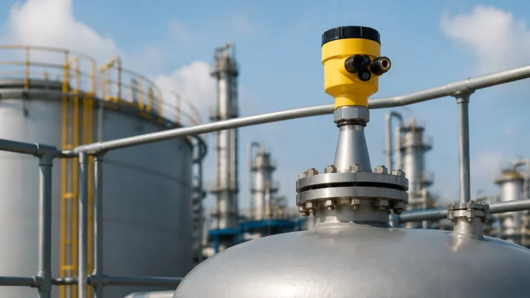
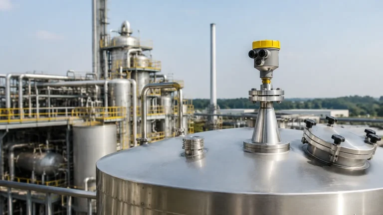
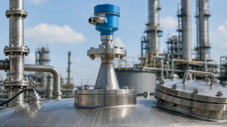
Radar Level Transmitter Datasheet
Radar Level Transmitter Datasheet: An Engineering Guide to Selection and Specification
In industrial process control, selecting the correct instrumentation requires a rigorous analysis of technical specifications. For engineers and procurement specialists, a radar level transmitter datasheet serves as the primary technical contract between the manufacturer and the end-user. It outlines the operational boundaries, accuracy limits, and environmental tolerances of the device.
Radar level measurement has become the industry standard for non-contact level sensing in sectors ranging from wastewater treatment to volatile chemical storage. However, misinterpreting the data provided in these documents can lead to signal loss, measurement drift, or premature hardware failure. This guide provides a factual breakdown of how to evaluate Radar Level Meters based on their technical datasheets and the physics of microwave propagation.
Understanding Radar Level Measurement Principles
Before diving into the specifics of a datasheet, it is essential to understand the two primary technologies used in modern radar level transmitters: Pulse Radar and Frequency-Modulated Continuous Wave (FMCW).
Pulse Radar (Time of Flight)
Pulse radar transmitters emit a short microwave pulse toward the product surface. The device measures the time it takes for the pulse to travel to the surface and return to the sensor. Since the speed of light is constant, the distance is calculated as:
*Distance = (Speed of Light × Time of Flight) / 2*
FMCW (Frequency-Modulated Continuous Wave)
FMCW radar, which is increasingly common in high-precision applications, emits a continuous signal with a constantly changing frequency. The transmitter compares the frequency of the received echo with the frequency of the signal being transmitted at that exact moment. The frequency difference is directly proportional to the distance. FMCW technology generally offers higher accuracy and better signal-to-noise ratios than pulse radar, making it the preferred choice for complex geometries or low-dielectric materials.
Key Parameters in a Radar Level Transmitter Datasheet
When reviewing a radar level transmitter datasheet, several critical parameters determine whether the instrument is fit for a specific industrial application.
1. Operating Frequency
Frequency is typically categorized into two bands: C-band (approx. 6 GHz) and K-band (26 GHz or 80 GHz).
- 26 GHz Radar: Offers a balance between signal strength and beam focus. It is suitable for most liquid applications.
- 80 GHz Radar: Features a very narrow beam angle (often as low as 3°). This is ideal for tall, narrow tanks or vessels with internal obstructions like agitators or heating coils.
2. Measuring Range and Blind Zone
The measuring range defines the maximum distance the radar can track (e.g., 30 meters or 120 meters). Equally important is the "blind zone" or "dead zone" (typically 100mm to 300mm from the sensor face), where the device cannot provide an accurate reading. Engineers must ensure the maximum fill level of the tank does not enter this blind zone.
3. Accuracy and Repeatability
Industrial-grade radar meters usually specify accuracy in millimeters (e.g., ±2mm or ±5mm). Repeatability refers to the device's ability to provide the same reading under identical conditions. For custody transfer or high-value chemical storage, high-precision FMCW units are required.
4. Dielectric Constant ($ε_r$)
The dielectric constant of the medium is perhaps the most critical factor in signal reflection. Materials with high dielectric constants (e.g., water, $ε_r ≈ 80$) reflect signals strongly. Hydrocarbons and oils have low dielectric constants ($ε_r < 2.5$), which result in weaker echoes. The datasheet will specify the minimum $ε_r$ the device can reliably detect.
Technical Specification Selection Table
The following table illustrates typical values found in a professional radar level transmitter datasheet for different application types.
| Feature | Standard Liquid Radar | High-Precision Solids Radar | Chemical/Corrosive Radar |
| :— | :— | :— | :— |
| Technology | 26 GHz Pulse | 80 GHz FMCW | 26 GHz Pulse/FMCW |
| Measuring Range | Up to 30m | Up to 120m | Up to 20m |
| Accuracy | ±3mm | ±2mm | ±5mm |
| Beam Angle | 8° – 10° | 3° – 4° | 10° – 12° |
| Process Temp. | -40°C to 150°C | -40°C to 250°C | -40°C to 130°C |
| Process Pressure | -1 to 40 bar | -1 to 10 bar | -1 to 3 bar |
| Antenna Material | Stainless Steel 316L | Stainless / Ceramic | PTFE / PVDF |
| Output Signal | 4-20mA / HART | 4-20mA / Modbus | 4-20mA / HART |
Installation Considerations and Constraints
Even the highest-spec instrument will fail if installation guidelines are ignored. A radar level transmitter datasheet usually includes mounting diagrams that must be followed strictly.
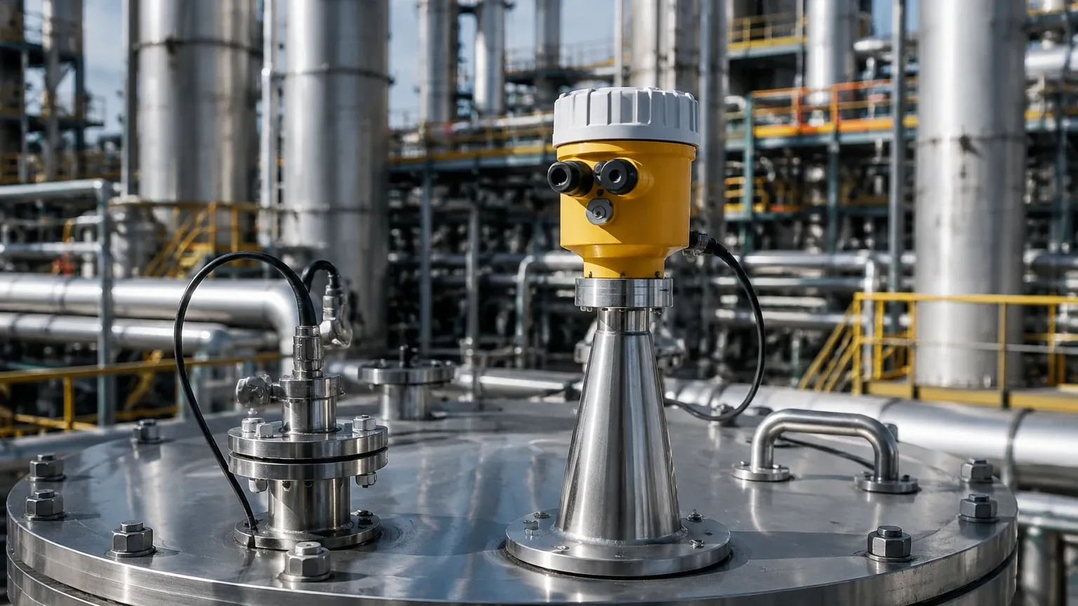
1. Nozzle Dimensions: The antenna should ideally extend beyond the mounting nozzle to prevent signal interference from the nozzle walls. If the nozzle is long, a high-frequency (80 GHz) radar is recommended due to its narrower beam.
2. Obstruction Clearance: The "keep-out zone" is defined by the beam angle. If a beam angle is 10°, the signal spreads as it travels. Any internal pipe, ladder, or agitator within that cone will create a false echo. Modern software can perform "false echo suppression," but physical clearance is always preferred.
3. Mounting Position: The transmitter should never be mounted in the center of a tank (to avoid multiple reflections from the walls) or too close to the wall (to avoid signal attenuation). A common rule of thumb is to mount the sensor at 1/6th to 1/4th of the tank diameter from the wall.
4. Orientation: For solid materials, the radar may need an adjustable flange (aiming device) to align the beam with the angle of repose of the material.
Limitations and Environmental Risks
While radar is highly versatile, certain process conditions listed in the datasheet can limit performance:
* Heavy Foam: Thick, dense foam can absorb microwave signals entirely, leading to a "Loss of Echo" (LOE) error. In such cases, a guided wave radar (GWR) or a low-frequency radar might be more effective.
* Turbulence: Rapidly moving liquid surfaces can scatter the signal. This is often mitigated by using a stilling well or bypass pipe, which provides a calm surface for measurement.
* Vapor and Condensation: While radar penetrates most vapors, heavy condensation on the antenna can attenuate the signal. Transmitters with PTFE-encapsulated antennas or air-purge connections are designed to handle these environments.
* Vacuum Conditions: Radar works effectively in a vacuum because electromagnetic waves do not require a medium for propagation (unlike ultrasonic sensors).
Why Data Accuracy Matters for International Procurement
For international buyers and OEMs, the radar level transmitter datasheet is a document of record. It ensures that the supplied equipment meets regional safety and telecommunications standards.
* Certifications: Check for ATEX/IECEx (explosion-proof) for hazardous areas, and SIL (Safety Integrity Level) ratings for critical overfill protection.
* Ingress Protection: For outdoor or wash-down environments, an IP67 or IP68 rating is mandatory.
* Communication Protocols: Ensure the output (HART, Profibus, Foundation Fieldbus, or RS485) is compatible with the existing PLC or SCADA system.
Welk provides detailed technical documentation for its range of Radar Level Meters, ensuring that engineers can match the instrument's capabilities to the specific dielectric, temperature, and pressure requirements of their process.
Frequently Asked Questions (FAQ)
Q: Can a radar level transmitter measure the interface between two liquids?
A: Standard non-contact radar is generally used for the top surface. For liquid-liquid interface (e.g., oil over water), Guided Wave Radar (GWR) is the standard choice as the signal can partially penetrate the upper layer.
Q: How does the dielectric constant affect the choice of antenna?
A: For low-dielectric materials, a larger antenna or a higher frequency (80 GHz) is often required to maximize the energy reflected back to the sensor.
Q: Is a radar transmitter affected by ambient temperature changes?
A: No. Unlike ultrasonic sensors, which depend on the speed of sound (which varies with air temperature and density), radar uses electromagnetic waves that are unaffected by air temperature, pressure, or vacuum.
Q: What is the benefit of a 4-wire vs. a 2-wire radar?
A: 2-wire (loop-powered) units are easier to install as they use the same wires for power and signal. 4-wire units have a separate power supply and are typically used for high-power applications or where extensive local displays and backlighting are required.
In conclusion, a radar level transmitter datasheet is more than a list of numbers; it is a roadmap for successful integration. By carefully matching the frequency, beam angle, and material compatibility to the specific needs of the facility, engineers can ensure long-term reliability and measurement precision in even the most challenging industrial environments.