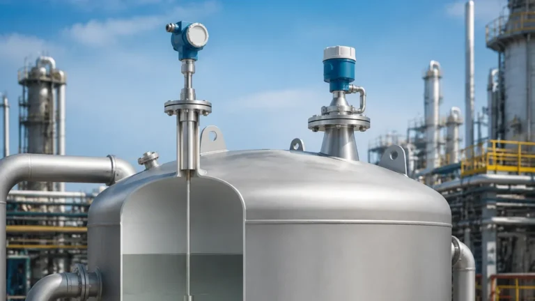
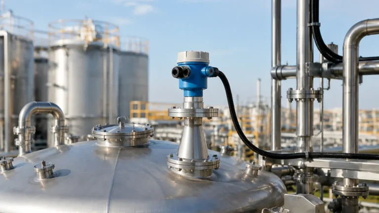
Radar Level Transmitter Em940
In the landscape of industrial automation, the precision of level measurement directly impacts process efficiency, safety, and inventory management. Among the various technologies available, Radar Level Meters have emerged as the industry standard for non-contact measurement in challenging environments. This guide provides a detailed technical analysis of the radar level transmitter em940, exploring its operating principles, engineering advantages, and practical application in modern industrial sectors.
1. The Evolution of Radar Level Measurement
Level measurement has transitioned from simple mechanical floats to sophisticated electronic sensors. While ultrasonic sensors were once the primary choice for non-contact measurement, they often struggle with environmental factors such as temperature fluctuations, vacuum conditions, and heavy dust. Radar technology overcomes these limitations by utilizing electromagnetic waves rather than sound waves.
The Radar Level Meters used in process industries today typically operate on one of two principles: Pulsed Radar or Frequency Modulated Continuous Wave (FMCW). The radar level transmitter em940 represents the high-frequency end of this technology spectrum, often utilizing the 80GHz band to provide superior resolution and signal focus compared to older 6GHz or 26GHz models.
1.1 Understanding the 80GHz Advantage
The frequency of a radar transmitter determines its beam angle and signal strength. A higher frequency, such as that found in the EM940 series, results in a narrower beam. For an engineer, this means the signal is less likely to be obstructed by internal tank structures like ladders, agitators, or heating coils. A narrower beam also allows for installation in smaller nozzles and provides a higher signal-to-noise ratio, which is critical when measuring liquids with low dielectric constants.
2. Measurement Principles of the Radar Level Transmitter EM940
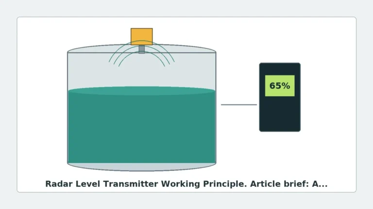
The radar level transmitter em940 primarily operates using the FMCW principle. Unlike pulsed radar, which measures the time it takes for a short burst of energy to return, FMCW transmits a continuous signal with a constantly changing frequency.
2.1 The FMCW Process
1. Signal Emission: The transmitter emits a continuous signal that sweeps across a frequency range (e.g., from 76GHz to 81GHz).
2. Reflection: The signal travels at the speed of light, hits the surface of the medium, and reflects back to the antenna.
3. Frequency Difference: Because the frequency of the emitted signal is constantly changing, by the time the reflection returns, there is a measurable difference between the frequency being transmitted and the frequency being received.
4. Distance Calculation: This frequency difference ($Δf$) is directly proportional to the time of flight and, consequently, the distance to the product surface.
This method allows for extremely high accuracy—often within ±1 mm (0.04 in)—making it suitable for custody transfer and high-precision process control.
3. Technical Specifications and Selection Criteria
When specifying a radar level transmitter em940, engineers must evaluate the hardware against the specific physical properties of the process. The EM940 is designed to handle a wide variety of media, from corrosive chemicals to dry solids.
3.1 Key Technical Parameters
| Feature | Specification (Typical EM940 Series) |
| :— | :— |
| Measuring Range | Up to 30m (98 ft) for liquids; 15m (49 ft) for solids |
| Frequency | 80GHz |
| Beam Angle | 3° to 8° (depending on antenna size) |
| Accuracy | ±1mm to ±3mm |
| Process Temperature | -40°C to +200°C (-40°F to +392°F) |
| Process Pressure | Vacuum to 4.0 MPa (40 bar) |
| Output Signal | 4-20mA / HART, Modbus RS485 |
| Antenna Material | PTFE, 316L Stainless Steel |
3.2 Dielectric Constant (εr) Considerations
The reflectivity of a medium depends on its dielectric constant. Water has a high dielectric constant (εr ≈ 80) and is easy to measure. Hydrocarbons, oils, and some plastic pellets have low dielectric constants (εr < 2.0), which reflect less energy. The high-frequency capability of the EM940 allows it to detect these weak reflections more reliably than lower-frequency radars.
4. Application Engineering: Where to Deploy the EM940
The radar level transmitter em940 is a versatile instrument, but its strengths are most apparent in specific industrial scenarios.
4.1 Chemical and Petrochemical Processing
In chemical reactors, internal obstructions and turbulent surfaces are common. The narrow 3° beam of the EM940 can be directed between an agitator blade and the tank wall, ensuring the level is tracked without interference. Furthermore, the use of PTFE-encapsulated antennas provides the necessary corrosion resistance for acids and bases.
4.2 Water and Wastewater Treatment
For large storage tanks or open channel flow measurement, the EM940 provides a maintenance-free alternative to ultrasonic sensors. It is unaffected by the high humidity, fog, or temperature layers that often occur above water surfaces in outdoor basins.
4.3 Food and Beverage Industry
Hygiene is paramount in food processing. The EM940 is available with flange connections and materials that meet sanitary standards. Its non-contact nature ensures there is no risk of product contamination, and it can withstand Clean-in-Place (CIP) cycles involving high-temperature steam and detergents.
5. Installation Best Practices and Constraints
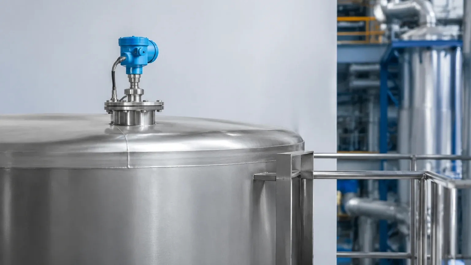
Proper installation is the most critical factor in the performance of any radar level transmitter. Even the most advanced 80GHz radar will fail if it is poorly positioned.
5.1 Nozzle Positioning and Dimensions
* Distance from Wall: The transmitter should ideally be installed at 1/4 to 1/6 of the tank diameter away from the side wall. Installing it too close to the wall can cause interference from the wall itself, while installing it in the dead center can lead to multiple reflections from the tank bottom or vertex.
* Nozzle Height: The nozzle should be as short as possible. If a long nozzle is required, the antenna must extend slightly beyond the bottom of the nozzle to prevent signal ringing within the pipe.
5.2 Avoiding Obstructions
Engineers must review the internal tank drawings before selecting a mounting point. Avoid installing the radar level transmitter em940 directly above:
* Inflow streams (which create turbulence and foam).
* Agitators (unless the narrow beam can bypass them).
* Heating coils or structural baffles.
5.3 Dead Zones (Blocking Distance)
Every radar has a "dead zone" or "blocking distance" near the antenna (typically 50mm to 200mm). The level cannot be measured accurately within this zone. Ensure the maximum expected liquid level does not enter this area.
6. Limitations and Application Risks
While highly capable, radar technology is not a universal solution. Engineers should be aware of the following risks:
* Heavy Foam: While radar can penetrate some light foam, dense, thick foam (like shaving cream) can absorb the radar signal entirely, leading to a "loss of echo" error. In such cases, a guided wave radar or a magnetic level gauge might be more appropriate.
* Extreme Turbulence: Rapidly boiling liquids or heavy splashing can scatter the radar signal. This can often be mitigated through software damping or the use of a stilling well (bypass pipe).
* Condensation and Buildup: Although 80GHz radars handle condensation better than 26GHz models, heavy crystalline buildup on the antenna lens will eventually attenuate the signal. Models with a "purge" connection allow for periodic cleaning with compressed air.
7. International Procurement: What Buyers Should Confirm
When sourcing a radar level transmitter em940 for international projects, technical documentation and certification are as important as the hardware itself. Buyers should verify:
1. Explosion-Proof Ratings: Ensure the device has the required ATEX, IECEx, or local equivalent certifications for hazardous zones.
2. Communication Protocols: Confirm whether the control system requires 4-20mA HART, Modbus, or Profibus.
3. Process Connection Standards: Specify whether flanges should follow ANSI, DIN, or JIS standards to ensure a proper fit during installation.
4. Calibration Reports: Request factory calibration certificates to ensure accuracy compliance before the unit leaves the manufacturer.
8. Frequently Asked Questions (FAQ)
Q: Can the EM940 measure solids like cement or grain?
A: Yes. The 80GHz frequency is particularly effective for solids because it reflects well off sloped surfaces (the "angle of repose") and can penetrate moderate dust clouds better than ultrasonic sensors.
Q: Does the EM940 require frequent recalibration?
A: No. Radar transmitters are solid-state devices with no moving parts. Once calibrated to the tank geometry during commissioning, they typically do not drift. Annual verification is recommended for safety-critical loops.
Q: How does the EM940 handle vacuum conditions?
A: Unlike ultrasonic sensors which require air to transmit sound, radar waves travel through a vacuum without any loss of signal. This makes the EM940 ideal for vacuum distillation columns.
Q: What is the difference between the EM940 and a Guided Wave Radar (GWR)?
A: The EM940 is a non-contact (free-space) radar. A GWR uses a physical probe (cable or rod) to guide the signal. GWR is better for extremely low dielectric liquids or foam, but the EM940 is preferred when the medium is corrosive, viscous, or when a probe cannot be inserted into the tank.
Conclusion
The radar level transmitter em940 represents a pinnacle of non-contact level measurement technology. By utilizing the 80GHz frequency band, it provides the precision, focus, and reliability required for complex industrial processes. Whether managing water resources or monitoring volatile chemical reactions, understanding the physics of the signal and the constraints of the installation environment allows engineers to leverage this tool to its full potential. For those seeking to upgrade their process instrumentation, selecting high-quality Radar Level Meters is a strategic investment in long-term operational stability.