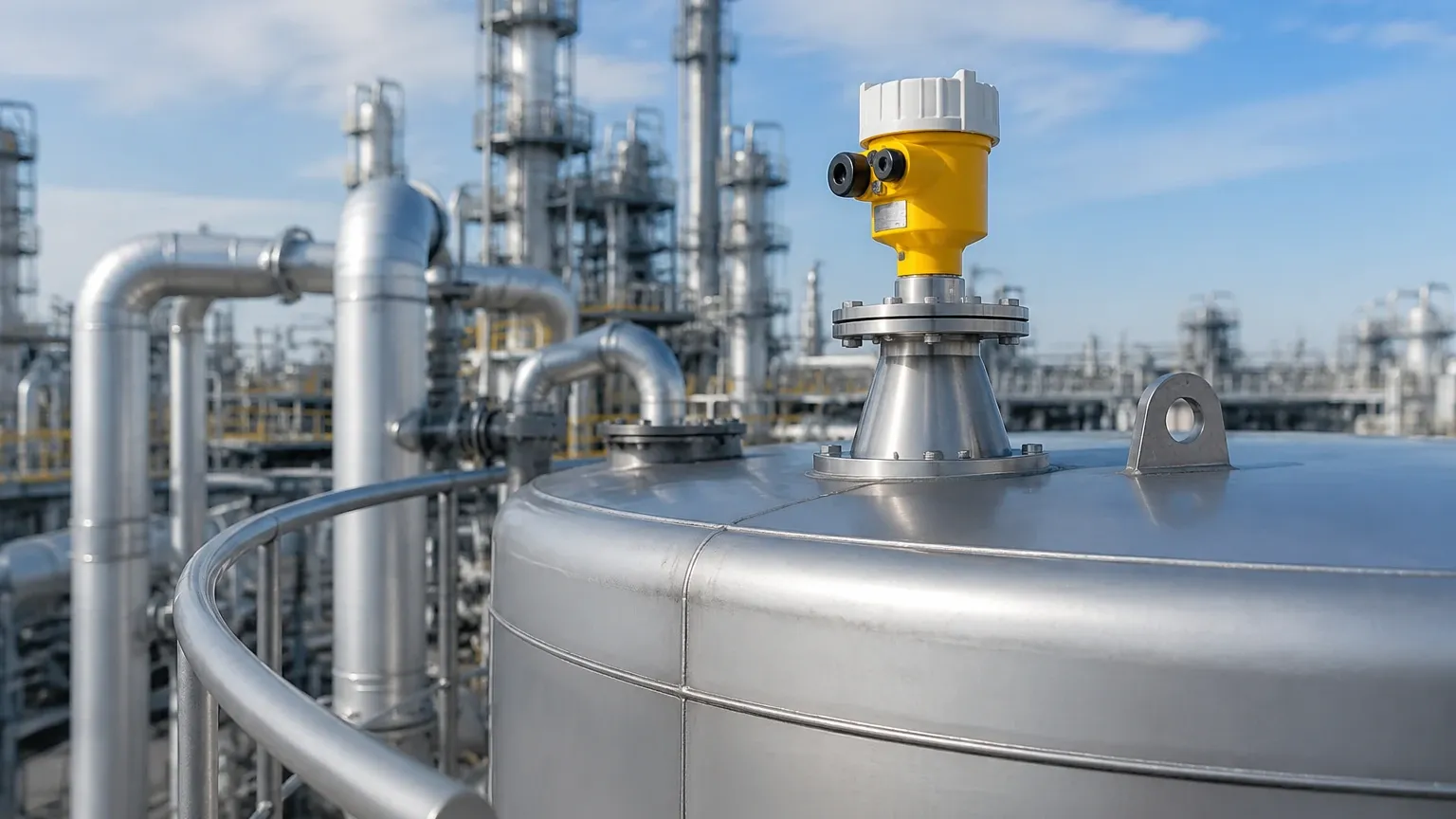
Radar Level Transmitter Image
Radar Level Transmitter Image: A Technical Guide to Signal Interpretation and Selection
In the field of industrial process automation, the ability to accurately monitor liquid and solid levels is critical for operational safety and efficiency. Among the various technologies available, Radar Level Meters have emerged as the gold standard for non-contact measurement in challenging environments. For instrumentation engineers and procurement specialists, understanding the "radar level transmitter image"—specifically the echo profile or signal visualization—is essential for successful commissioning and troubleshooting.
This guide provides a comprehensive technical overview of radar level measurement principles, the interpretation of signal images, and practical selection criteria for industrial applications.
Understanding Radar Level Measurement Principles
Radar level measurement is based on the Time of Flight (ToF) principle. The instrument emits high-frequency electromagnetic waves (microwaves) toward the process medium. These waves reflect off the surface of the material and return to the antenna. Since the speed of electromagnetic waves is constant (the speed of light), the distance to the material surface can be calculated by measuring the time elapsed between emission and reception.
There are two primary methods used in modern industrial radar transmitters:
1. Pulsed Radar
This technology emits short microwave pulses. The transmitter measures the time it takes for a single pulse to travel to the surface and back. While effective for many standard applications, pulsed radar typically has a lower signal-to-noise ratio compared to continuous wave methods.
2. FMCW (Frequency Modulated Continuous Wave)
FMCW radar emits a continuous signal with a constantly changing frequency. The distance is determined by the frequency difference between the transmitted signal and the reflected signal at any given moment. FMCW is widely regarded as superior for high-accuracy requirements and complex environments because it provides better signal processing capabilities and a more detailed "image" of the tank interior.
The Significance of the Radar Level Transmitter Image (Echo Profile)
In technical terms, a "radar level transmitter image" refers to the echo curve or envelope curve generated by the device's signal processor. This visualization is typically accessed via specialized software or a local HMI (Human-Machine Interface). It represents the amplitude of reflected signals (in decibels) plotted against the distance from the transmitter.
Components of the Echo Profile
* The Emission Pulse: The initial peak representing the signal leaving the antenna.
* The Level Echo: The primary peak corresponding to the surface of the material being measured.
* False Echoes: Secondary peaks caused by internal tank obstructions such as agitators, heating coils, ladders, or structural beams.
* The Threshold (MAP): A digital line defined during commissioning that allows the transmitter to ignore reflections below a certain amplitude or those identified as static obstructions.
Interpreting this image is vital. A clean, sharp peak indicates a high-reflectivity surface (high dielectric constant), while a broad or weak peak may suggest foam, turbulence, or a low-dielectric medium. Modern Radar Level Meters utilize advanced algorithms to perform "False Echo Suppression," effectively "learning" the internal image of an empty tank to distinguish between the product level and fixed obstacles.
Technical Comparison: 26GHz vs. 80GHz Technology
The frequency of the radar signal significantly impacts the quality of the echo image and the reliability of the measurement.
| Feature | 26GHz Radar | 80GHz Radar |
| :— | :— | :— |
| Beam Angle | Wider (typically 8° to 20°) | Narrow (typically 3° to 4°) |
| Signal Precision | Standard (±3mm to ±5mm) | High (up to ±1mm) |
| Antenna Size | Larger horn antennas required | Compact lens antennas |
| Obstruction Handling | Prone to interference from tank walls | Easily avoids internal obstructions |
| Dust/Steam Penetration | Excellent | Good (improved by signal processing) |
| Typical Application | Large storage tanks, simple liquids | Small vessels, agitators, high-precision solids |
Selection Criteria for Industrial Applications
Choosing the correct radar level transmitter requires an analysis of the physical and chemical properties of the application. Engineers should consult the following factors before finalizing a specification:
1. Dielectric Constant (εr)
The dielectric constant of the medium determines how much energy is reflected back to the sensor. Water has a high εr (~80) and produces a strong echo image. Hydrocarbons, such as oils and solvents, have low εr values (1.4 to 2.5), resulting in weaker reflections. For extremely low dielectric materials, Guided Wave Radar (GWR) or high-sensitivity 80GHz non-contact radar is recommended.
2. Process Conditions
* Temperature and Pressure: High-pressure reactors or cryogenic storage require specialized flange seals and antenna materials (e.g., PTFE, PEEK, or Ceramics).
* Turbulence and Foam: Surface agitation can scatter the radar signal. In these cases, software filters or stilling wells may be necessary to stabilize the radar level transmitter image.
3. Vessel Geometry
The presence of internal structures determines the required beam angle. A narrow beam (80GHz) is preferable for tall, narrow silos or tanks with complex internals to prevent the signal from clipping the vessel walls or reflecting off unintended targets.
Installation Best Practices and Constraints
Correct installation is the most influential factor in maintaining a clear signal image. Failure to follow these guidelines often results in "lost echoes" or erratic readings.
1. Nozzle Height and Diameter: The antenna should extend slightly beyond the mounting nozzle to prevent "ringing" or internal reflections within the nozzle itself. The nozzle should be smooth and free of burrs.
2. Positioning: Do not install the transmitter in the center of a tank with a domed roof, as this can cause multiple reflections to converge at the sensor. Ideally, the unit should be placed at 1/4 to 1/6 of the tank diameter from the wall.
3. Avoid the Fill Stream: Never install the radar where the microwave beam will intersect the path of incoming material. This creates significant noise in the echo profile.
4. Polarization Alignment: For rectangular tanks or those with specific structural beams, rotating the transmitter to align the signal polarization can help minimize interference.
Limitations of Radar Technology
While highly versatile, radar level meters are not universal solutions. Engineers must account for the following limitations:
* Heavy Foam: Certain types of dense, conductive foam can absorb the microwave signal entirely, preventing any reflection from reaching the sensor. In such cases, a magnetic level gauge or a displacement transmitter may be more appropriate.
* Vacuum Effects: While microwaves travel through a vacuum, the mechanical seals of the transmitter must be rated for vacuum service to prevent damage to the electronics.
* Minimum Measuring Distance (Blind Zone): All radar sensors have a "dead zone" or blocking distance near the antenna (typically 50mm to 200mm) where measurement is not possible.
Troubleshooting via Signal Diagnostics
When a radar transmitter fails to provide a steady reading, the first step is to examine the radar level transmitter image (the echo curve). Common diagnostic scenarios include:
* Multiple Peaks at the Top: Often caused by condensation or buildup on the antenna lens. Using a PTFE drop antenna or an air-purge system can mitigate this.
* Flatline Signal: If the echo curve shows no distinct peaks beyond the emission pulse, the signal may be absorbed by the medium (low εr) or scattered by heavy foam.
* Ghost Echoes: If a peak appears at a distance twice the actual level, it is likely a double-bounce reflection. This can be resolved by adjusting the damping or the false echo suppression map.
Frequently Asked Questions (FAQ)
Q: Can radar level meters measure through plastic tanks?
A: Yes. Non-contact radar signals can penetrate non-conductive materials like plastic, fiberglass (FRP), and glass. This allows for measurement from outside the tank, provided the material is not shielded by metal.
Q: What is the difference between a 2-wire and 4-wire radar transmitter?
A: A 2-wire (loop-powered) transmitter uses the same pair of wires for power and the 4-20mA signal, which is standard for most industrial automation. A 4-wire transmitter has separate power leads, allowing for higher power consumption, which is sometimes needed for advanced signal processing or integrated heaters in extremely cold environments.
Q: How does dust affect the radar level transmitter image in solids measurement?
A: High-frequency radar (80GHz) is generally effective at penetrating dust. However, extremely thick dust clouds can attenuate the signal. In these environments, selecting a transmitter with a high dynamic range and using an air-purge connection to keep the antenna face clean is essential.
Q: Is calibration required for radar level meters?
A: Unlike hydrostatic transmitters, radar meters do not require periodic re-calibration because they measure distance based on the constant speed of light. However, a "zero-point" verification and a span check are recommended during initial commissioning to ensure the transmitter's reference point matches the tank's physical dimensions.
Conclusion
Modern radar level measurement provides an unparalleled combination of accuracy and reliability. By understanding the technical nuances of the radar level transmitter image and selecting equipment based on frequency, dielectric properties, and vessel constraints, industrial operators can ensure long-term stability in their level monitoring processes. For complex applications, partnering with a professional manufacturer like Welk ensures access to the customized OEM/ODM services and technical support necessary to optimize instrument performance in the field.