Radar Level Transmitter Mounting
Radar Level Transmitter Mounting: A Comprehensive Engineering Guide
In the field of industrial process automation, the accuracy of level measurement is often determined not by the instrument's internal electronics, but by how it is physically integrated into the vessel. Radar level meters have become the gold standard for non-contact measurement due to their immunity to temperature fluctuations, vacuum conditions, and high pressure. However, achieving the millimetric precision promised by manufacturers requires a deep understanding of radar level transmitter mounting principles.
This guide explores the technical foundations of radar technology, the geometry of signal propagation, and the practical mounting configurations required to ensure reliable performance in challenging industrial environments.
Understanding Radar Measurement Principles
Before addressing mounting specifics, it is essential to understand how Radar Level Meters interact with their environment. Most modern industrial radar transmitters utilize one of two primary technologies: Pulse Radar or Frequency Modulated Continuous Wave (FMCW).
Pulse Radar (Time of Flight)
Pulse radar emits a high-frequency microwave signal toward the product surface in short bursts. The instrument measures the "Time of Flight" (ToF)—the time it takes for the pulse to travel to the surface and return to the antenna. Because the speed of light is constant, the distance is calculated as:
*Distance = (Speed of Light × Time) / 2*
FMCW Radar
FMCW radar transmits a continuous signal with a constantly changing frequency. The reflection from the product surface is received and compared to the frequency being transmitted at that moment. The frequency difference is directly proportional to the distance. FMCW is generally preferred for high-accuracy applications and environments with significant turbulence or low dielectric constants, as it provides a better signal-to-noise ratio.
The Role of Frequency
The frequency of the radar (typically 6GHz, 26GHz, or 80GHz) dictates the beam angle. Higher frequencies, such as 80GHz, produce a narrower beam. This is a critical factor in radar level transmitter mounting because a narrower beam is less likely to interact with tank walls or internal obstructions like agitators and ladders.
Critical Mounting Geometry and Positioning
The physical placement of the radar transmitter on the tank roof is the most influential factor in signal integrity. Engineers must balance the need for a clear line of sight with the physics of microwave reflection.
1. Distance from the Tank Wall
A radar transmitter should never be mounted in the exact center of a tank, nor should it be mounted too close to the wall.
- Avoid the Center: In many tanks, the roof is slightly arched or conical. Mounting in the center can cause multiple reflections to converge, amplifying noise and creating "ghost" echoes.
- Wall Proximity: If the transmitter is too close to the wall, the radar beam will reflect off the side of the tank, causing signal attenuation or false high-level readings.
- The Rule of Thumb: Mount the transmitter at a distance of 1/4 to 1/6 of the tank diameter from the side wall. For example, in a 4-meter (13.1 ft) diameter tank, the ideal mounting position is approximately 0.6 to 1 meter from the wall.
2. Beam Angle and Obstructions
The radar signal propagates in a cone shape. Any metallic object within this cone—such as heating coils, support struts, or limit switches—will reflect the signal. While modern software can "map out" these static reflections (False Signal Suppression), it is best practice to provide a clear path.
To calculate the beam diameter at the bottom of the tank, use the formula:
*D = 2 × L × tan(α/2)*
Where *D* is the beam diameter, *L* is the distance (tank height), and *α* is the beam angle specified by the manufacturer.
Nozzle and Standpipe Considerations
Most industrial vessels utilize nozzles for instrument mounting. However, the nozzle itself can interfere with the radar signal if not designed correctly.
Nozzle Height and Diameter
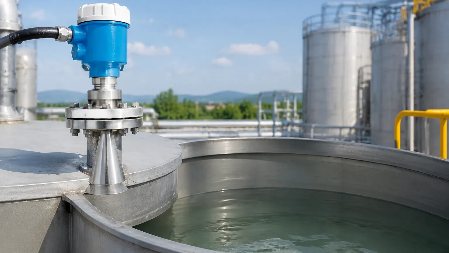
The antenna of the radar level meter should ideally extend 10mm (0.4 in) or more beyond the bottom of the nozzle. If the antenna is recessed within a long, narrow nozzle, the microwave energy will reflect off the nozzle's interior walls, creating a large "ringing" effect that masks the signal near the top of the tank (the Dead Zone).
If a long nozzle is unavoidable, engineers should specify a wave-guide or a standpipe. A standpipe (a perforated pipe extending to the bottom of the tank) acts as a conduit for the radar signal, eliminating interference from foam, turbulence, or internal tank structures.
Mounting on Standpipes (Stillwells)
When using a standpipe, the radar signal is constrained within the pipe. This is ideal for liquids with low dielectric constants (like hydrocarbons) because the pipe concentrates the signal energy. Ensure the pipe is smooth, vertical, and has a vent hole at the top to equalize pressure and liquid levels.
Radar Level Transmitter Mounting Selection Table
Choosing the right mounting hardware depends on the process pressure, temperature, and the nature of the medium.
| Mounting Type | Best For | Advantages | Limitations |
| :— | :— | :— | :— |
| Threaded (NPT/G) | Small tanks, chemical totes | Low cost, easy installation | Limited to lower pressures; requires a matching boss |
| Flanged (ANSI/DIN) | Process vessels, high pressure | Robust seal, handles high temp/pressure | More expensive; requires larger tank openings |
| Sanitary (Tri-Clamp) | Food, Beverage, Pharma | No crevices for bacteria growth | Specific to hygienic industries |
| Bracket/Aiming Flange | Open channels, solids/bulk | Allows aiming the beam to the angle of repose | Not pressure-rated; open to atmosphere |
| Isolation Valve | Hazardous liquids | Allows sensor removal without depressurizing | Increases nozzle height; may require antenna extensions |
Practical Installation Checklist
When executing a radar level transmitter mounting plan, follow these technical steps to ensure long-term reliability:
1. Alignment: Ensure the transmitter is mounted perfectly vertical. Even a 1-degree tilt can significantly reduce the signal strength returned from a flat liquid surface.
2. Inflow Streams: Never mount the radar directly above the tank's filling inlet. The falling liquid or solids will cause erratic readings and may damage the antenna.
3. Dead Zone (Blocking Distance): Be aware of the manufacturer's specified dead zone (typically 50mm to 300mm). The liquid level should never rise into this zone, or the sensor will lose track of the surface.
4. Environmental Protection: Use a sunshade if the transmitter is installed outdoors in hot climates to prevent electronic drift and extend the life of the LCD display.
5. Cable Entry: Always point cable entries downward and use drip loops to prevent moisture from entering the housing via the conduit.
Limitations and Application Risks
While radar is highly versatile, certain conditions can challenge even the best-mounted Radar Level Meters:
* Low Dielectric Constants (εr): Materials like liquid nitrogen or certain oils reflect very little energy. In these cases, a guided wave radar or a standpipe mounting is necessary to concentrate the signal.
* Heavy Foam: Thick, dense foam can absorb the radar signal entirely. If foam is present, a lower frequency (6GHz) radar or a different technology like a magnetic level gauge may be required.
* Vapor and Condensation: While radar penetrates vapor, heavy condensation on the antenna lens can cause signal attenuation. In these environments, look for transmitters with PTFE-encapsulated antennas or integrated air-purge systems to keep the lens clear.
Frequently Asked Questions (FAQs)
Q: Can I mount a radar transmitter on a plastic tank without a nozzle?
A: Yes. Radar signals can penetrate plastic and fiberglass. You can mount the transmitter above a plastic tank, and it will read through the tank roof, provided the material is not conductive and there is no metal reinforcement.
Q: How do I handle mounting in a tank with a heavy agitator?
A: Use a high-frequency (80GHz) radar with a narrow beam angle to "miss" the agitator blades. Additionally, use the software's False Signal Suppression (Envelope Curve) to teach the radar to ignore the blades when they pass through the beam.
Q: Does the mounting position change for solids vs. liquids?
A: Yes. For solids, the material forms a cone (angle of repose). The radar should be mounted with an aiming flange to tilt the antenna perpendicular to the slope of the material for maximum signal return.
Conclusion
Successful radar level transmitter mounting is a combination of geometric precision and process awareness. By selecting the correct mounting location—away from the center and walls—and ensuring the nozzle design does not interfere with the signal cone, engineers can eliminate the majority of measurement errors. Whether dealing with corrosive chemicals or bulk solids, following these industrial standards ensures that your level measurement system remains accurate, safe, and maintenance-free for years to come.