Ultrasonic or Radar Level Transmitter
Ultrasonic or Radar Level Transmitter: An Engineering Selection Guide
In industrial process control, selecting the appropriate non-contact level measurement technology is a critical decision that impacts both operational safety and long-term maintenance costs. For engineers and procurement specialists, the choice often narrows down to an ultrasonic or radar level transmitter. While both technologies offer the advantage of measuring level without contacting the medium, their physical principles, environmental tolerances, and cost profiles differ significantly.
This guide provides a factual, technical comparison of these two technologies to assist in specifying the correct instrument for water treatment, chemical processing, and general industrial automation.
1. Measurement Principles
Before evaluating which sensor is appropriate for a specific application, it is essential to understand the underlying physics that govern their performance.
1.1 Ultrasonic Level Measurement
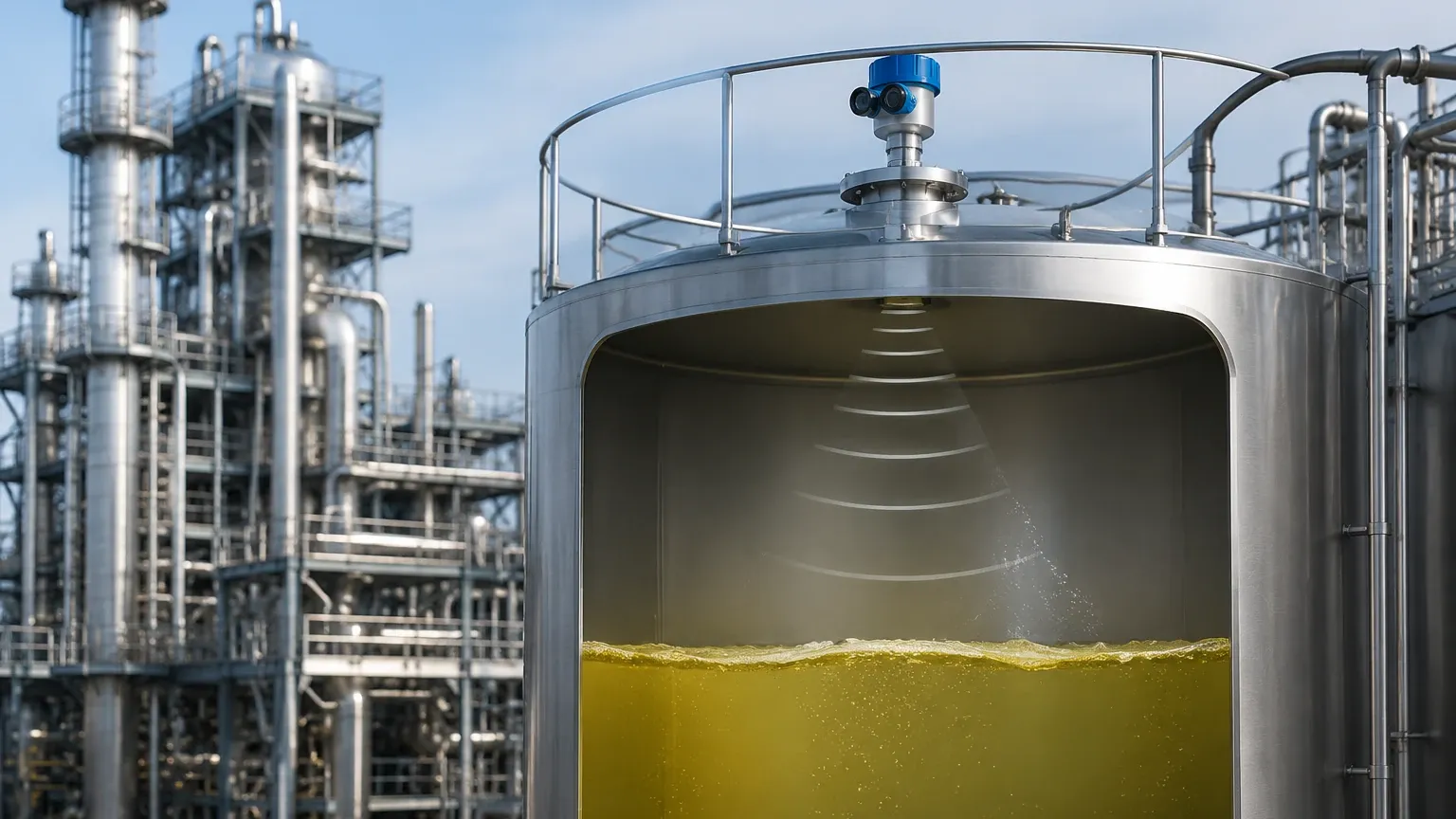
Ultrasonic transmitters utilize a piezoelectric crystal to generate high-frequency mechanical sound waves. These waves travel through the air space above the medium, reflect off the surface, and return to the transducer. The instrument calculates the distance based on the "time-of-flight" (ToF) and the known speed of sound in air.
Because sound requires a medium (gas) to travel, the accuracy of an ultrasonic sensor is directly tied to the density and temperature of the air. Most modern ultrasonic sensors include an integrated temperature sensor to compensate for changes in the speed of sound, which varies by approximately 0.17% per degree Celsius. However, they cannot operate in a vacuum and are highly sensitive to gas composition changes (e.g., high concentrations of CO2 or methane) which alter sound velocity.
1.2 Radar Level Measurement
Radar Level Meters utilize high-frequency electromagnetic (EM) waves, typically in the microwave spectrum (6GHz to 80GHz). Unlike sound waves, EM waves do not require a medium and travel at the speed of light. The sensor emits a signal, which is reflected back by the medium’s surface due to the change in dielectric constant (Dk).
There are two primary types of radar technology used in level measurement:
* Pulse Radar: Measures the time it takes for a short microwave pulse to travel to the surface and back.
* FMCW (Frequency Modulated Continuous Wave): The transmitter emits a continuous signal with a varying frequency. The difference in frequency between the emitted and received signal is proportional to the distance. FMCW is generally preferred for high-precision industrial applications due to its superior signal-to-noise ratio.
2. Comparing Ultrasonic and Radar Technologies
Deciding between an ultrasonic or radar level transmitter requires an analysis of the process environment. While ultrasonic sensors are often more cost-effective for simple water-based applications, radar technology offers higher reliability in complex process conditions.
2.1 Environmental Factors
* Vacuum and Pressure: Ultrasonic sensors cannot function in a vacuum because sound waves cannot propagate without a medium. High pressure also attenuates sound waves. Radar, being electromagnetic, is unaffected by vacuum and can operate at pressures exceeding 40 bar (4.0 MPa).
* Temperature Extremes: High temperatures create vapor layers and temperature gradients that refract sound waves, leading to measurement errors in ultrasonic devices. Radar is largely immune to temperature fluctuations within the vapor space.
* Steam and Condensation: Steam can absorb or reflect ultrasonic signals, causing signal loss. While heavy condensation can affect radar antennas, many high-frequency radar units (80GHz) use specialized lens antennas that are self-cleaning or less susceptible to droplet interference.
* Dust and Foam: In solid level measurement, heavy dust can attenuate ultrasonic signals. Radar, especially lower frequency models (26GHz), can penetrate dust clouds more effectively. Foam, however, remains a challenge for both; light, airy foam may be transparent to radar but reflective to ultrasonic, while thick, dense foam may absorb both signals.
2.2 Material Properties
The dielectric constant (Dk) of the medium is the most critical factor for radar. Materials with a low Dk (e.g., oil, plastic pellets) reflect less energy than water-based liquids. Ultrasonic sensors, conversely, rely on the mechanical density of the surface and are indifferent to the dielectric properties of the material.
3. Technical Selection Matrix
The following table summarizes the suitability of each technology across common industrial parameters:
| Parameter | Ultrasonic Transmitter | Radar Level Meter |
| :— | :— | :— |
| Measuring Range | Up to 15–30 meters | Up to 30–120 meters |
| Accuracy | ±0.25% to ±0.5% of range | ±1mm to ±3mm |
| Vacuum Compatibility | No | Yes |
| High Pressure (>3 bar) | Limited | Excellent |
| High Temperature (>80°C)| No | Yes (up to 250°C+) |
| Corrosive Vapors | Moderate (requires PTFE) | Excellent |
| Cost | Lower | Higher |
| Best Use Case | Open channels, sumps, water tanks | Chemical reactors, pressurized vessels, silos |
4. Installation Considerations
Proper installation is paramount for both technologies to ensure a clear signal path and minimize false echoes.
4.1 Dead Zones (Blocking Distance)
Every non-contact sensor has a "dead zone" or blocking distance directly beneath the sensor face where measurement is impossible. For ultrasonic sensors, this is typically 0.2m to 0.8m depending on the frequency. Radar units generally have smaller dead zones, sometimes as low as 0.05m, allowing for better utilization of tank capacity.
4.2 Beam Angle and Obstructions
The beam angle determines the "footprint" of the signal at a given distance.
* Ultrasonic: Typically has a wider beam angle (8° to 15°). If the tank has internal ladders, agitators, or heating coils, the sound waves may reflect off these obstructions instead of the liquid surface.
* Radar: High-frequency radar (80GHz) offers very narrow beam angles (as low as 3°). This allows the sensor to be installed in narrow nozzles or tanks with complex internal structures without interference.
4.3 Mounting Position
* Perpendicularity: The sensor must be mounted perpendicular to the liquid surface. A tilt of even a few degrees can cause the reflected signal to miss the receiver, especially on calm liquid surfaces.
* Nozzle Height: For radar, the antenna should ideally extend slightly past the mounting nozzle to prevent "ringing" or internal reflections within the nozzle neck.
5. Application Risks and Limitations
Engineers must be aware of specific failure modes associated with an ultrasonic or radar level transmitter:
1. Acoustic Noise: In ultrasonic applications, high-frequency noise from pneumatic filling or heavy machinery can interfere with the sensor’s signal processing.
2. Surface Turbulence: Rapidly splashing liquids can scatter signals. In these cases, using a stilling well or bypass pipe is recommended for both technologies to provide a calm surface for measurement.
3. Dielectric Shifts: If a radar meter is calibrated for a high-Dk liquid and the process switches to a low-Dk hydrocarbon, the signal strength may drop significantly, requiring a recalibration of the sensitivity thresholds.
4. Coating and Buildup: If the medium is prone to crystallization or coating, the sensor face (ultrasonic) or antenna (radar) may become obscured. Ultrasonic sensors are particularly sensitive to this as the mechanical vibration of the transducer is dampened by the coating.
6. International Buyer’s Checklist
When procuring level instrumentation for global projects, confirm the following technical specifications with the manufacturer to ensure site compatibility:
* Power Supply: Determine if the site requires 2-wire (loop-powered) or 4-wire (separate power) configurations. 24V DC is standard, but some remote locations may require AC power.
* Signal Output: Ensure the device supports the local control system protocols (e.g., 4-20mA with HART, Modbus RS485, or Profibus).
* Process Connection: Verify flange standards (ANSI, DIN, or JIS) and thread types (NPT or G). Incorrect threading is a common cause of installation delays.
* Hazardous Area Ratings: Confirm if the installation environment requires ATEX, IECEx, or UL/CSA explosion-proof or intrinsically safe certifications.
* Material Compatibility: Specify the wetted materials. While PVDF is common for ultrasonic, radar antennas may require 316L Stainless Steel, PTFE, or Hastelloy for aggressive chemical environments.
7. Frequently Asked Questions (FAQ)
Q: Can I use an ultrasonic sensor on a tank with a vacuum?
A: No. Sound waves require a gaseous medium to travel. In a vacuum, there is no medium to carry the sound, so the sensor will fail to receive an echo.
Q: Is radar always better than ultrasonic?
A: Not necessarily. For simple, ambient-pressure water storage or open-channel flow measurement in wastewater, ultrasonic sensors are highly reliable and significantly more cost-effective.
Q: How does the dielectric constant affect radar measurement?
A: The dielectric constant (Dk) determines how much of the electromagnetic energy is reflected back to the sensor. Water has a high Dk (~80) and reflects a strong signal. Oils and solvents have low Dk values (1.9 to 4.0) and reflect much weaker signals, requiring more sensitive radar electronics.
Q: What is the impact of heavy foam on these sensors?
A: Foam is the most challenging condition for non-contact level measurement. Light foam may allow radar to see through to the liquid, while ultrasonic might reflect off the top of the foam. Very dense, thick foam often absorbs both signals, in which case a contact technology like a magnetic level gauge or a hydrostatic transmitter may be more appropriate.
By understanding the fundamental differences between an ultrasonic or radar level transmitter, engineering teams can select the most robust solution for their specific process requirements, ensuring accurate data and minimizing downtime.