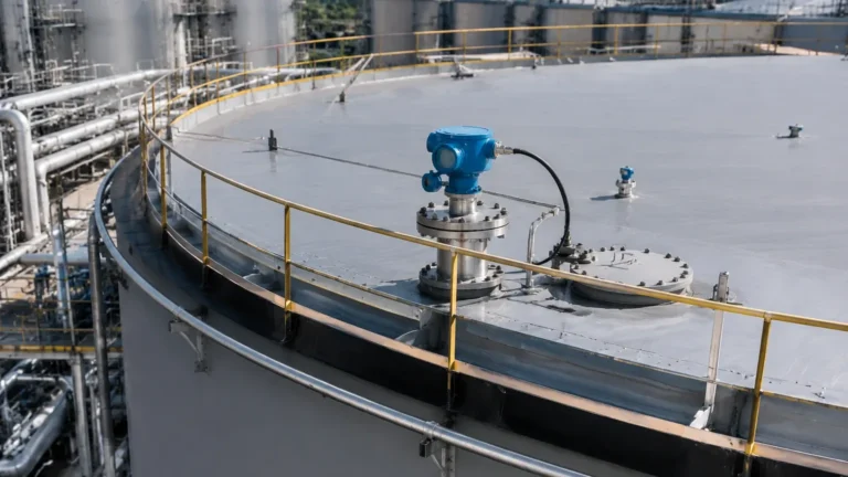
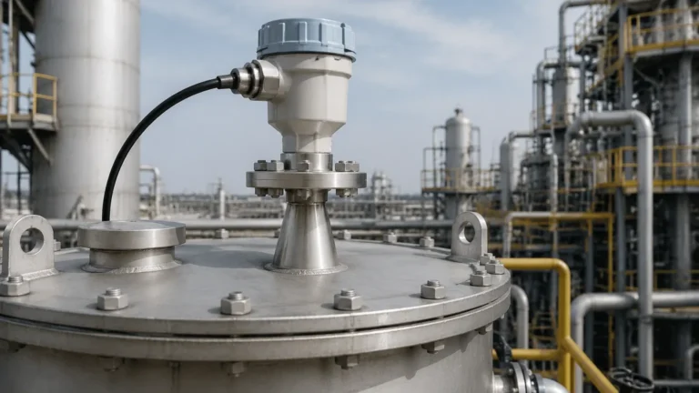
Vega Radar Level Transmitter Manual PDF
Vega Radar Level Transmitter Manual PDF
In the field of industrial automation, precise level measurement is a cornerstone of process safety, inventory management, and operational efficiency. Engineers and technicians frequently search for resources such as a vega radar level transmitter manual pdf to resolve specific installation challenges or to calibrate high-precision instruments. However, a manual is only as effective as the engineering foundation upon which the instrument is selected. Understanding the core principles, application constraints, and selection criteria for Radar Level Meters is essential before any technical documentation can be effectively utilized.
This guide provides a technical overview of radar level measurement technology, bridging the gap between raw manual data and practical field application. We will examine the physics of radar signals, the differences between various radar technologies, and the critical factors that dictate successful deployment in B2B industrial environments.
1. Understanding Radar Measurement Principles
Radar level measurement is a non-contact or guided-contact technology that utilizes electromagnetic waves to determine the distance to a product surface. Unlike ultrasonic sensors, which rely on sound waves and are affected by air temperature and pressure, radar waves travel at the speed of light and are largely immune to atmospheric conditions.
Time of Flight (ToF) vs. FMCW
Two primary methods are used to calculate level based on radar waves:
1. Pulse Radar (Time of Flight): The sensor emits a short microwave pulse that travels to the product surface, reflects, and returns to the receiver. The distance is calculated based on the transit time ($D = c \times t / 2$, where $c$ is the speed of light). This method is traditionally robust and energy-efficient.
2. Frequency Modulated Continuous Wave (FMCW): The sensor emits a continuous signal with a constantly changing frequency. The difference between the frequency of the emitted signal and the reflected signal at any given moment is proportional to the distance. FMCW is widely regarded for its superior accuracy and signal-to-noise ratio, particularly in complex tank geometries.
The Role of Frequency
The frequency of the radar signal—typically ranging from 6 GHz to 80 GHz—determines the beam angle and the ability of the sensor to handle foam, dust, or condensation. Higher frequencies (e.g., 80 GHz) allow for smaller antenna sizes and narrower beam angles, which are critical for avoiding internal tank obstructions like agitators or heating coils.
2. Technology Comparison: Guided Wave vs. Non-Contact
When reviewing a vega radar level transmitter manual pdf or similar technical documentation, you will notice a distinction between Guided Wave Radar (GWR) and Non-contact Radar. Choosing between them depends on the physical properties of the medium and the vessel configuration.
Guided Wave Radar (GWR)
GWR uses a physical probe (rod or cable) to guide the microwave signal to the surface. This is particularly effective for:
* Low Dielectric Media: Liquids with low dielectric constants (e.g., hydrocarbons) provide weak reflections. The probe concentrates the signal energy, ensuring a reliable return.
* Interface Measurement: GWR is the industry standard for measuring the interface between two liquids (e.g., oil and water).
* Turbulent Surfaces: The probe acts as a stabilizer, preventing signal loss due to surface ripples or foam.
Non-Contact Radar
Non-contact radar meters are mounted at the top of the vessel and emit waves through the air. These are preferred for:
* Corrosive or Abrasive Media: Since the sensor does not touch the material, maintenance requirements are significantly reduced.
* Hygienic Applications: In food and pharmaceutical industries, non-contact sensors prevent contamination risk.
* Extreme Temperatures: High-temperature processes are easier to manage when the electronics are physically separated from the medium.
3. Technical Selection Criteria
Selecting the correct instrument requires more than just matching a part number from a manual. Engineers must evaluate several process variables to ensure long-term reliability.
Dielectric Constant ($ε_r$)
The dielectric constant of the material is the most critical factor in radar measurement. It determines how much energy is reflected back to the sensor. Materials with high $ε_r$ (e.g., water, $ε_r ≈ 80$) are easy to measure, while those with low $ε_r$ (e.g., plastic pellets or liquefied gases, $ε_r < 2.0$) require high-sensitivity sensors or GWR.
Process Pressure and Temperature
Standard radar sensors can handle temperatures from -40°C to 200°C (-40°F to 392°F), but specialized high-temperature versions can exceed 450°C (842°F). Similarly, pressure ratings must be checked against the vessel's design limits, especially in pressurized chemical reactors.
Selection Table: Radar Technology Comparison
| Parameter | Guided Wave Radar (GWR) | 26 GHz Non-Contact | 80 GHz Non-Contact |
| :— | :— | :— | :— |
| Measuring Range | Up to 75m (246 ft) | Up to 30m (98 ft) | Up to 120m (393 ft) |
| Accuracy | ±2 mm | ±3 mm | ±1 mm |
| Beam Angle | N/A (Follows Probe) | 10° – 20° | 3° – 8° |
| Foam Resistance | High | Moderate | Low (Frequency dependent) |
| Dust Resistance | High | Moderate | Excellent |
| Installation | Requires probe clearance | Requires clear path | Minimal clearance needed |
4. Installation Considerations and Best Practices
Proper installation is the primary factor in preventing "false echoes" or signal loss. Most technical manuals emphasize the following guidelines:
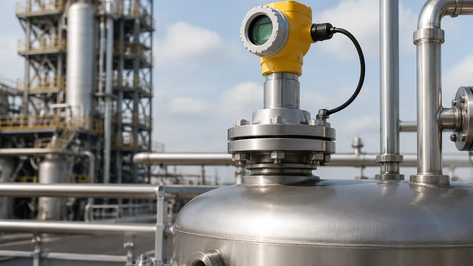
1. Nozzle Design: The radar antenna should ideally extend slightly beyond the bottom of the mounting nozzle to prevent signal interference from the nozzle walls. If a long nozzle is unavoidable, a higher frequency (80 GHz) radar is recommended due to its narrow beam.
2. Obstruction Clearance: Radar waves spread in a cone. Any internal structure (ladders, pipes, agitators) within this cone will create a reflection. While modern software can "map out" these false echoes, it is best to install the sensor in a location with a clear line of sight to the product surface.
3. The 1/6th Rule: For cylindrical tanks with torispherical or elliptical heads, the ideal mounting position is often 1/6th of the tank diameter away from the side wall. Mounting in the center can cause multiple reflections that interfere with the primary signal.
4. Inflow Streams: Never install the radar sensor directly over the filling stream. The turbulence and the material falling through the air will cause significant signal noise.
5. Limitations and Application Risks
While radar is a highly versatile technology, it is not a "one-size-fits-all" solution. Engineers should be aware of the following limitations:
* Heavy Foam: Extremely thick, dense foam (like shaving cream) can absorb the radar signal entirely, leading to a "loss of echo" error. In these cases, GWR or hydrostatic transmitters may be more appropriate.
* Condensation and Buildup: While 80 GHz radar can often see through light condensation, heavy buildup of conductive or viscous material on the antenna can attenuate the signal. Sensors with PTFE drop antennas or air purging systems are used to mitigate this.
* Vacuum Conditions: While the radar signal itself is unaffected by a vacuum, the mechanical seals and gaskets of the transmitter must be rated for vacuum service to prevent air ingress or sensor damage.
6. Maintenance and Troubleshooting
When a fault occurs, referring to the vega radar level transmitter manual pdf will provide specific error codes (e.g., F013 for "Loss of Echo"). General troubleshooting steps include:
* Check the Echo Curve: Most modern radar level meters allow users to view the echo curve via a handheld communicator or laptop. A healthy curve shows a sharp peak at the product surface and minimal noise elsewhere.
* Verify Dielectric Settings: If the level reading is consistently off, the dielectric constant programmed into the transmitter may be incorrect for the medium being measured.
* Signal Mapping: If the tank is empty but the sensor shows a high level, a false reflection from an internal structure may need to be suppressed using the "False Signal Suppression" or "Background Mapping" feature.
Frequently Asked Questions (FAQ)
Q: Can radar measure the level of solids?
A: Yes. However, solids measurement requires a radar with a high dynamic range to handle the irregular reflections from sloped surfaces and dust. 80 GHz radar is typically the preferred choice for silos and bunkers.
Q: How does the beam angle affect installation?
A: A narrower beam angle (e.g., 3°) allows the sensor to be mounted closer to the tank wall or in vessels with many internal obstructions without picking up interference.
Q: Is radar level measurement safe for hazardous areas?
A: Yes, most industrial radar transmitters are available with ATEX, IECEx, or FM certifications for use in explosive atmospheres (Class I, Div 1/2).
Q: Does the color of the liquid affect the measurement?
A: No. Unlike optical sensors, radar is unaffected by the color, transparency, or opacity of the liquid.
Conclusion
Successful level measurement in industrial environments requires a combination of robust hardware and precise engineering. While a vega radar level transmitter manual pdf provides the necessary technical data for a specific device, the selection of the right technology—whether it be 80 GHz non-contact radar for a chemical reactor or guided wave radar for an oil-water separator—is the most critical step. By understanding the principles of electromagnetics and the specific constraints of the process environment, engineers can ensure accurate, maintenance-free level monitoring for years to come. For those seeking specialized solutions, exploring the latest advancements in Radar Level Meters will provide the necessary tools to optimize even the most challenging industrial applications.