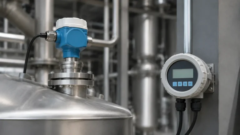
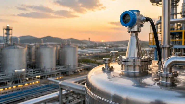
Yokogawa Radar Type Level Transmitter
Yokogawa Radar Type Level Transmitter: An Engineering Guide to Selection and Application
In the landscape of industrial process automation, precise level measurement is a cornerstone of safety, efficiency, and inventory management. Among the various technologies available, radar-based systems have emerged as the gold standard for non-contact measurement in challenging environments. This guide examines the technical architecture of the yokogawa radar type level transmitter, its operating principles, and the engineering considerations required to integrate Radar Level Meters into modern industrial infrastructures.
Understanding Radar Level Measurement Principles
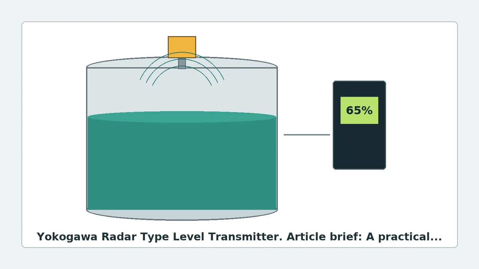
Before selecting a specific instrument, it is essential to understand the physics of microwave propagation and reflection. Radar level transmitters operate on the principle of Time Domain Reflectometry (TDR) or Frequency Modulated Continuous Wave (FMCW) technology. These devices emit electromagnetic pulses or continuous waves that travel at the speed of light, reflect off the surface of the process medium, and return to the sensor.
1. Pulse Radar (Time-of-Flight)
Pulse radar transmitters emit a microwave signal in short bursts. The instrument measures the time elapsed between the emission of the pulse and the reception of the echo. Since the speed of light is constant, the distance to the product surface is calculated using the formula:
$$D = \frac{c \cdot t}{2}$$
Where:
* D is the distance to the surface.
* c is the speed of light (~300,000 km/s).
* t is the measured transit time.
2. FMCW (Frequency Modulated Continuous Wave)
Modern high-end units, including many configurations of the yokogawa radar type level transmitter, often utilize FMCW technology. Instead of discrete pulses, the transmitter emits a continuous signal with a constantly changing frequency (a frequency sweep). The reflection from the liquid surface is received and compared to the signal being emitted at that exact moment. The difference in frequency (the beat frequency) is directly proportional to the distance. FMCW is generally preferred for high-accuracy applications and environments with significant noise or turbulence.
Key Features of Yokogawa Radar Type Level Transmitters
Industrial-grade radar transmitters are designed to withstand the rigors of chemical processing, oil and gas extraction, and power generation. The following features are typically found in high-performance radar units:
* Multi-Reflection Suppression: Advanced signal processing algorithms that distinguish between the true level echo and false echoes generated by internal tank structures like agitators, heating coils, or ladders.
* High-Frequency Operation: Units operating at 24 GHz or 80 GHz provide narrower beam angles, which are critical for avoiding obstructions in tall, narrow vessels.
* Non-Contact Sensing: Because the sensor does not touch the medium, it is immune to the corrosive effects of acids, the viscosity of heavy oils, and the hygiene requirements of food and beverage processing.
* Digital Integration: Support for HART, FOUNDATION Fieldbus, and PROFIBUS protocols ensures seamless integration into existing Distributed Control Systems (DCS).
Selection Criteria for Industrial Applications
Choosing the correct Radar Level Meters requires a thorough analysis of the process conditions. Engineers must evaluate several variables to ensure long-term reliability.
Dielectric Constant (εr)
The dielectric constant of the medium is the most critical factor in radar measurement. It determines how much of the microwave energy is reflected back to the sensor.
* High εr (>10): Water-based liquids provide strong reflections and are easy to measure.
* Low εr (1.4 to 4): Hydrocarbons, solvents, and liquefied gases reflect very little energy. In these cases, high-sensitivity FMCW transmitters or guided wave radar may be necessary.
Vessel Geometry and Internal Obstructions
The beam angle of the transmitter determines the "footprint" of the radar signal at the bottom of the tank. If the beam hits a ladder or an agitator, it creates a false echo.
* 80 GHz Transmitters: Offer beam angles as narrow as 3°, making them ideal for vessels with complex internals.
* 6 GHz to 26 GHz Transmitters: Better suited for applications where heavy foam or steam is present, as lower frequencies penetrate vapors more effectively.
Process Temperature and Pressure
Radar antennas must be selected based on the flange temperature and tank pressure. Standard PTFE (Polytetrafluoroethylene) seals are suitable for moderate temperatures (up to 150°C), while ceramic seals and cooling extensions are required for high-temperature reactors exceeding 250°C.
Technical Selection Table
| Application | Recommended Technology | Frequency | Typical Accuracy | Max Range |
| :— | :— | :— | :— | :— |
| Large Storage Tanks (Oil/Water) | FMCW / Pulse | 10 – 26 GHz | ±2 mm | 35m |
| Small Process Vessels w/ Agitators | FMCW | 80 GHz | ±1 mm | 100m |
| Corrosive Chemical Storage | Non-contact (PTFE Lens) | 24 – 80 GHz | ±3 mm | 20m |
| High-Pressure Steam Drums | Guided Wave Radar | N/A | ±5 mm | 10m |
| Bulk Solids / Silos | FMCW | 80 GHz | ±5 mm | 120m |
Installation Guidelines and Constraints
Proper installation is paramount to the performance of a yokogawa radar type level transmitter. Failure to follow geometric constraints often leads to signal loss or erratic readings.
1. Nozzle Height and Diameter: The antenna should ideally extend slightly below the bottom of the mounting nozzle to prevent "ringing" or internal nozzle reflections. If the nozzle is long and narrow, a high-frequency (80 GHz) unit is required to keep the beam from hitting the nozzle walls.
2. Mounting Position: Never mount the transmitter in the center of a tank with a domed roof, as this can cause multiple reflections to converge at the sensor. The ideal position is usually 1/4 to 1/3 of the tank diameter from the wall.
3. Avoid the Inflow Stream: The transmitter should be positioned away from the point where product enters the tank. Turbulence and air entrainment in the inflow stream can scatter the radar signal.
4. Agitator Interference: If an agitator is present, the transmitter should be configured with a "False Echo Map" or "Empty Tank Spectrum." This allows the software to ignore static reflections from the blades.
Limitations and Application Risks
While radar is highly versatile, it is not a universal solution. Engineers should be aware of the following risks:
* Heavy Foam: Dense, thick foam can absorb microwave signals entirely, leading to a "Loss of Echo" (LOE) error. In such cases, a low-frequency radar or a different technology like a magnetic level gauge may be more appropriate.
* Vacuum Conditions: While radar works in a vacuum, the transition through the process seal (the window between the electronics and the tank) must be carefully engineered to prevent leaks.
* Condensation and Buildup: Heavy condensation on the antenna lens can attenuate the signal. Many modern Radar Level Meters utilize convex lens designs or air purging systems to mitigate this effect.
Maintenance and Troubleshooting
Radar transmitters are generally low-maintenance due to their lack of moving parts. However, the following routine checks are recommended:
* Signal Strength Monitoring: Most digital transmitters provide a "Signal-to-Noise Ratio" (SNR) value. A declining SNR over time may indicate buildup on the antenna or a degrading seal.
* Verification: Periodic verification against a manual dip-tape measurement is standard practice in regulated industries to ensure the instrument calibration has not drifted.
* Software Updates: Ensure the signal processing firmware is up to date, as manufacturers frequently release improvements for echo tracking in turbulent conditions.
Frequently Asked Questions (FAQ)
Q: Can a radar transmitter measure the interface between two liquids?
A: Standard non-contact radar is generally used for the top surface level. For liquid-liquid interface (e.g., oil over water), Guided Wave Radar (GWR) is typically the preferred technology as it can detect the change in dielectric constant at the interface layer.
Q: How does the dielectric constant affect the range of the transmitter?
A: The lower the dielectric constant, the less energy is reflected. This effectively reduces the maximum measurable range. For example, a unit that can measure water at 30 meters might only be able to measure a light hydrocarbon at 15 meters.
Q: Is 80 GHz always better than 24 GHz?
A: Not necessarily. While 80 GHz offers a narrower beam and better resolution, 24 GHz or lower frequencies are often better at penetrating heavy dust, steam, or vapors which can attenuate higher-frequency signals.
Q: What is the impact of tank pressure on radar accuracy?
A: In most liquid applications, pressure has a negligible effect on the speed of microwaves. However, in high-pressure gas phases (like high-pressure steam), the speed of light slightly changes, which may require a gas phase compensation factor to maintain millimeter accuracy.
Conclusion
The implementation of a yokogawa radar type level transmitter offers a robust solution for complex industrial level measurement tasks. By understanding the interplay between frequency, dielectric constants, and vessel geometry, engineers can specify a system that minimizes maintenance and maximizes process uptime. For those seeking a wider range of options or customized configurations, exploring various Radar Level Meters is the first step toward achieving precise and reliable automation control.