0 10v Ultrasonic Water Tank Level Sensor
0-10V Ultrasonic Water Tank Level Sensor: An Engineering Guide to Selection and Application
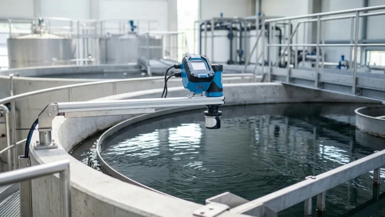
In modern industrial automation and building management systems (BMS), the requirement for non-contact, reliable, and easily integrated level measurement is paramount. The 0 10v ultrasonic water tank level sensor has emerged as a standard solution for monitoring water levels in everything from municipal storage tanks to industrial process vessels. By utilizing high-frequency sound waves and converting the distance data into a standardized voltage signal, these instruments provide a bridge between physical fluid dynamics and digital control logic.
As a professional manufacturer, Welk specializes in high-precision Ultrasonic Level Meters designed to withstand the rigors of industrial environments while maintaining the accuracy required for critical level control. This guide examines the technical principles, selection criteria, and installation best practices for 0-10V ultrasonic sensors.
Understanding the Measurement Principle
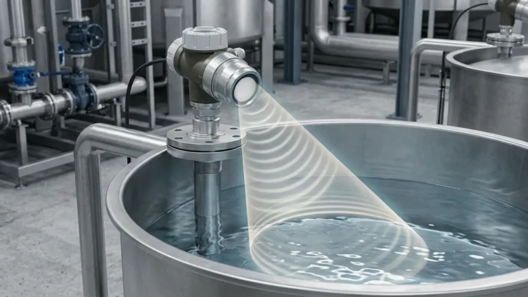
Ultrasonic level measurement is based on the "Time of Flight" (ToF) principle. The sensor’s transducer emits a series of ultrasonic pulses (typically between 20 kHz and 200 kHz) toward the surface of the water. These sound waves travel through the air, strike the water surface, and reflect back toward the sensor.
The sensor’s internal microprocessor measures the time interval between the emission of the pulse and the reception of the echo. Since the speed of sound in air is a known constant (approximately 340 m/s at 20°C), the distance to the water surface can be calculated using the following formula:
Distance = (Speed of Sound × Time) / 2
Once the distance is calculated, the device subtracts this value from the total tank height (programmed during calibration) to determine the actual water level. This level is then scaled to a 0-10V analog output signal, where 0V typically represents an empty tank and 10V represents a full tank (or vice-versa, depending on the configuration).
Why Choose a 0-10V Output?
While 4-20mA current loops are common in long-distance industrial telemetry, the 0 10v ultrasonic water tank level sensor is highly favored in specific B2B contexts, particularly in HVAC, laboratory automation, and localized PLC (Programmable Logic Controller) systems.
1. Direct Compatibility: Many standard PLCs and data acquisition boards feature high-impedance voltage inputs. A 0-10V signal can be wired directly without the need for external shunt resistors.
2. Simplicity in Testing: Maintenance technicians can verify sensor performance using a standard digital multimeter set to DC voltage, making on-site troubleshooting faster and more intuitive.
3. Low Power Consumption: In battery-powered or solar-powered remote monitoring stations, voltage-based signals often consume less power than continuous current loops.
Key Evaluation Criteria for Selection
When specifying an ultrasonic sensor for a water tank application, engineers must look beyond the output signal. The following factors determine the reliability of the measurement.
1. Measurement Range and Dead Zone
Every ultrasonic sensor has a "Dead Zone" (also known as the blocking distance) directly beneath the transducer face. In this zone, the sensor cannot accurately process the returning echo because the transducer is still vibrating from the pulse emission. For a standard 5-meter range sensor, the dead zone is typically between 0.25m and 0.35m. The tank should be designed such that the maximum water level never enters this dead zone.
2. Beam Angle
The ultrasonic pulse is not a laser; it spreads out in a conical shape. The beam angle (usually between 5° and 12°) dictates how much space the sensor needs to avoid false reflections from tank walls, internal ladders, or inlet pipes. A narrower beam angle is generally preferred for tall, narrow tanks.
3. Environmental Protection
For water tank applications, the sensor is often exposed to high humidity and potential splashing. An IP66 or IP67 rating is essential. If the tank contains corrosive chemicals or is located in a coastal area, PVDF (Polyvinylidene Fluoride) transducers are recommended over standard ABS or PP plastics.
Selection Table: Welk Ultrasonic Series Comparison
| Feature | Compact Series (Short Range) | Standard Industrial Series | Extended Range Series |
| :— | :— | :— | :— |
| Measurement Range | 0.3m – 5m | 0.4m – 10m | 0.6m – 20m |
| Output Signal | 0-10V / 4-20mA / RS485 | 0-10V / 4-20mA / RS485 | 0-10V / 4-20mA / RS485 |
| Accuracy | ±0.3% FS | ±0.25% FS | ±0.2% FS |
| Beam Angle | 10° – 12° | 8° – 10° | 5° – 8° |
| Dead Zone | 0.25m | 0.35m | 0.5m – 0.8m |
| Housing Material | ABS / Nylon | Cast Aluminum / Plastic | Cast Aluminum |
| Application | Small tanks / Sumps | Process water / Chemical storage | Large reservoirs / Silos |
Installation Considerations
Correct installation is the single most important factor in ensuring the longevity and accuracy of an ultrasonic level meter. Follow these practical engineering guidelines:
* Vertical Alignment: The sensor face must be perfectly parallel to the water surface. Even a few degrees of tilt can cause the echo to reflect away from the transducer, resulting in signal loss.
* Avoid the Center: In cylindrical tanks with domed tops, do not mount the sensor in the exact center. This can create a "parabolic mirror" effect that amplifies noise and multiple echoes. Ideally, mount the sensor at 1/2 the radius of the tank.
* Inlet Interference: Ensure the sensor is positioned away from the water inlet. Falling water creates turbulence and air bubbles that scatter the ultrasonic signal.
* Standoff Pipes: If you must mount the sensor on a nozzle or standoff pipe, ensure the pipe's inner diameter is smooth and wide enough to prevent the beam from hitting the pipe walls. The pipe length should be kept as short as possible to minimize the dead zone impact.

Limitations and Challenges
While highly versatile, 0-10V ultrasonic water tank level sensors are not suitable for every environment. Engineers should be aware of the following limitations:
1. Foam and Turbulence: Heavy foam on the water surface acts as an acoustic absorber, significantly weakening the echo. In such cases, a radar level meter or a hydrostatic pressure sensor may be more appropriate.
2. Temperature Gradients: The speed of sound changes with air temperature. While Welk sensors include integrated temperature compensation, rapid fluctuations or extreme temperature layers in very tall tanks can introduce small errors.
3. Vacuum or High Pressure: Ultrasonic waves require a medium (air/gas) to travel. They cannot function in a vacuum. Furthermore, high-pressure environments change the density of the air, affecting the speed of sound beyond the limits of standard compensation algorithms.
4. Signal Interference: Electrical noise from large motors or VFDs (Variable Frequency Drives) can interfere with the 0-10V analog signal if shielded cabling is not used. Always use twisted-pair shielded cables for signal transmission.
Maintenance and Troubleshooting
Ultrasonic sensors are generally low-maintenance because they have no moving parts. However, periodic checks are recommended:
* Transducer Cleaning: In high-humidity environments, condensation or mineral buildup can occur on the transducer face. Wipe the face gently with a soft cloth and mild detergent. Do not use abrasive materials or solvents.
* Signal Validation: Periodically compare the 0-10V output against a manual dip-tape measurement to ensure the calibration hasn't drifted due to environmental changes.
* Cable Integrity: Check for signs of corrosion or moisture ingress in the junction box, especially if the sensor is installed outdoors.
Frequently Asked Questions (FAQs)
Q: Can a 0-10V ultrasonic sensor be used for wastewater?
A: Yes, as long as there is no heavy foam or thick floating debris. For wastewater sumps, we recommend a sensor with an IP68 rating and a chemical-resistant transducer face.
Q: What is the maximum distance I can run a 0-10V signal?
A: Unlike 4-20mA signals, voltage signals are susceptible to voltage drops over long distances. For 0-10V, it is best to keep the cable run under 15–20 meters. For longer distances, consider using RS485 (Modbus) or converting to a 4-20mA loop.
Q: How does the sensor handle a tank with an internal agitator?
A: Advanced Ultrasonic Level Meters from Welk feature "False Echo Suppression" software. This allows the user to program the sensor to ignore static reflections from internal structures like agitator blades or brackets.
Q: Does the 0-10V signal require a separate power supply?
A: Most 0-10V ultrasonic sensors are 3-wire or 4-wire devices. They typically require a 24V DC power supply to operate the electronics and generate the output voltage.
Conclusion
The 0 10v ultrasonic water tank level sensor remains a cornerstone of industrial level measurement due to its non-contact nature and ease of integration. By understanding the acoustic principles and adhering to strict installation standards, facility managers can achieve precise, maintenance-free monitoring of their water assets. For complex applications involving narrow tanks, agitated liquids, or chemical storage, selecting a high-quality instrument from a dedicated manufacturer like Welk ensures long-term operational reliability.