Ultrasonic Level Sensor for Solids
Ultrasonic Level Sensor for Solids: Engineering Guide for Bulk Material Measurement
In industrial process automation, accurately measuring the level of bulk solids presents a unique set of challenges compared to liquid level monitoring. While liquids typically provide a flat, horizontal reflecting surface, solids are characterized by uneven topographies, varying particle sizes, and the presence of dust. The ultrasonic level sensor for solids has emerged as a preferred non-contact solution for many of these applications, offering a balance of reliability and cost-effectiveness. This guide examines the technical principles, selection criteria, and installation best practices for deploying ultrasonic technology in solids environments.
Understanding the Measurement Principle
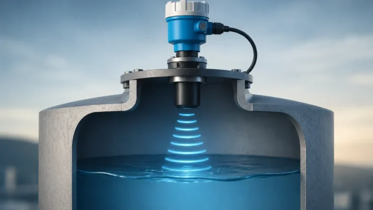
Ultrasonic level measurement is based on the "Time-of-Flight" (ToF) principle. The sensor, typically mounted at the top of a silo, bin, or hopper, contains a piezoelectric transducer that converts electrical energy into mechanical vibrations. These vibrations generate high-frequency sound waves (ultrasonic pulses) that travel through the air toward the material surface.
When the sound waves encounter the solid material, a portion of the energy is reflected back toward the sensor. The transducer then acts as a receiver, converting the returning sound energy back into an electrical signal. The internal electronics of the Ultrasonic Level Meters calculate the distance to the material surface using the following formula:
Distance = (Speed of Sound × Time Delay) / 2
Since the speed of sound in air is approximately 343 meters per second (at 20°C), the device can precisely determine the distance by measuring the time elapsed between the pulse emission and the echo reception. By subtracting this distance from the total height of the vessel (the "tank height"), the instrument determines the actual level of the solids.
The Impact of Temperature and Atmosphere
Because the speed of sound varies with air temperature (increasing by approximately 0.17% per degree Celsius), most industrial ultrasonic sensors include an integrated temperature probe. This allows the device to perform real-time compensation, ensuring accuracy even as ambient temperatures fluctuate within the silo.
Technical Challenges Specific to Solids
Measuring solids requires the sensor to overcome physical phenomena that are not present in liquid applications. Understanding these factors is critical when selecting an ultrasonic level sensor for solids.
1. Angle of Repose and Surface Geometry
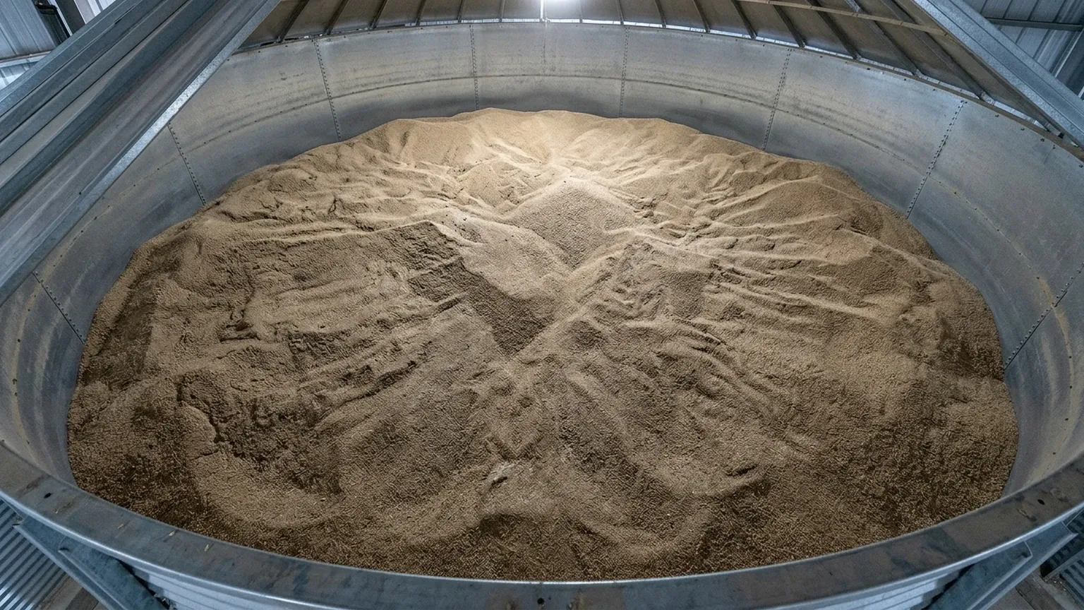
When bulk solids are loaded into a vessel, they naturally form a conical shape known as the "angle of repose." Conversely, during discharge, a cone-shaped depression (funneling) often occurs. Unlike a flat liquid surface, these sloping surfaces reflect ultrasonic waves away from the sensor rather than directly back to it. This can result in a weakened echo signal or "signal loss."
2. Signal Absorption and Porosity
Solid materials vary in density and texture. Coarse, hard materials like stone or plastic pellets reflect sound waves effectively. However, soft or porous materials—such as fine powders, flour, or sawdust—tend to absorb sound energy. This absorption reduces the amplitude of the returning echo, requiring sensors with higher power or advanced signal processing algorithms.
3. Dust and Acoustic Noise
Filling operations for solids often generate significant amounts of dust. While ultrasonic waves can penetrate moderate dust, extremely dense dust clouds can scatter or attenuate the signal. Furthermore, the mechanical noise generated by pneumatic conveying systems or heavy machinery can interfere with the ultrasonic frequency, necessitating the use of sophisticated noise-filtering software within the meter.
Key Selection Criteria for Solids Applications
Selecting the right instrument involves more than just matching the measurement range. Engineers must evaluate several technical specifications to ensure long-term reliability.
| Feature | Requirement for Solids | Reason |
| :— | :— | :— |
| Frequency | Lower (e.g., 10 kHz to 30 kHz) | Lower frequencies have longer wavelengths, which penetrate dust better and travel further. |
| Beam Angle | Narrow (e.g., 5° to 10°) | Minimizes interference from silo walls, internal ladders, and structural supports. |
| Transducer Power | High Output | Necessary to overcome signal absorption by porous materials and scattering from sloped surfaces. |
| Self-Cleaning | Recommended | Vibrations of the transducer face help prevent dust buildup on the sensor head. |
| Mounting | Adjustable Flange | Allows the sensor to be aimed at the material's angle of repose to maximize echo recovery. |
Measurement Range Considerations
While many Ultrasonic Level Meters are rated for ranges up to 30 or 40 meters, these ratings are often based on ideal liquid reflections. For solids, it is a standard engineering practice to "derate" the sensor's effective range by 30% to 50% to account for signal loss due to surface unevenness and dust. For a silo 15 meters tall, a sensor rated for 30 meters is often the safer choice.
Installation and Positioning Strategies
Correct installation is the most influential factor in the performance of an ultrasonic level sensor for solids. Follow these guidelines to ensure optimal signal integrity:
1. Avoid the Fill Stream: Never mount the sensor directly above the point where material enters the silo. The falling material will block the ultrasonic pulses and cause erratic readings.
2. Distance from Walls: Mount the sensor at least 0.5 to 1 meter away from the silo wall. If the sensor is too close, the "beam spread" (the conical path of the sound wave) will hit the wall, creating false echoes.
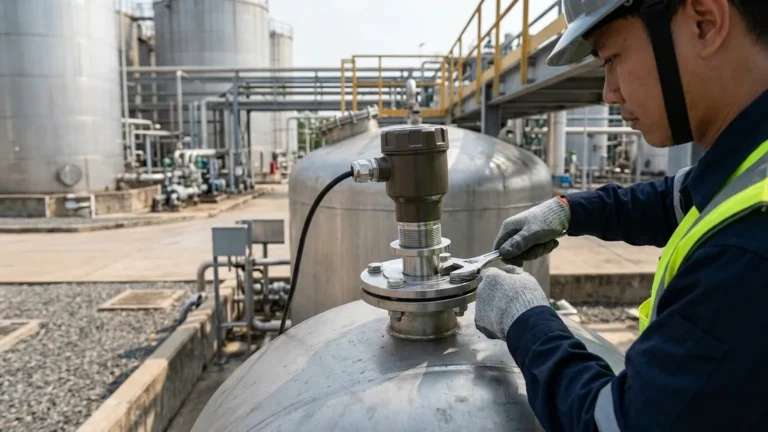
3. Aiming the Transducer: For solids, the sensor should generally be aimed toward the discharge outlet or the center of the material pile. Using an adjustable swivel flange (aiming kit) allows the technician to tilt the sensor to find the strongest possible echo return from the sloped surface.
4. The "Dead Zone" (Blocking Distance): Every ultrasonic sensor has a near-field dead zone (typically 0.2m to 0.8m) where it cannot measure. Ensure the sensor is mounted high enough that the material never enters this zone, even when the silo is at maximum capacity.
5. Standpipe Considerations: If using a mounting nozzle or standpipe, the pipe must be smooth on the inside and as short as possible. Long, narrow nozzles can create internal reflections that mask the actual material level.
Limitations and When to Consider Alternatives
While ultrasonic technology is versatile, it is not a "one-size-fits-all" solution. There are specific conditions where other technologies, such as Radar (FMCW) or Guided Wave Radar (GWR), may be more appropriate:
* High Pressure or Vacuum: Ultrasonic waves require a medium (air or gas) to travel. They cannot function in a vacuum and are significantly affected by high-pressure environments that change the air density.
* Extreme Dust: In applications like cement production or fly ash silos where dust is constant and extremely thick, high-frequency Radar level meters are often preferred because electromagnetic waves are unaffected by dust.
* Extreme Temperatures: If the process temperature exceeds 100°C to 150°C, the transducer materials in an ultrasonic sensor may degrade. Radar or heavy-duty mechanical systems are better suited for high-heat environments.
Maintenance and Troubleshooting
Modern ultrasonic level sensor for solids designs are largely maintenance-free due to their non-contact nature. However, periodic checks are recommended:
* Dust Buildup: In very sticky or humid environments, dust may cake onto the transducer face. While many Welk sensors feature self-cleaning vibrations, a manual wipe-down every six months may be necessary in extreme cases.
* Echo Profiles: Use the device's diagnostic software to view the "echo curve." A healthy curve shows a distinct peak at the material level. If the peak is small and surrounded by "noise," the sensor may need to be re-aimed.
* Calibration Check: Periodically verify the sensor's reading against a manual tape measure (when safe to do so) to ensure the temperature compensation is functioning correctly.
Frequently Asked Questions (FAQ)
Q: Can ultrasonic sensors measure solids in tall, narrow silos?
A: Yes, provided the sensor has a narrow beam angle (typically <10°). This prevents the signal from reflecting off the silo walls before reaching the material.
Q: How does the particle size of the solid affect measurement?
A: Larger particles (like rocks or large pellets) provide better reflective surfaces. Very fine powders (like talcum or flour) tend to absorb more sound, requiring a more powerful transducer.
Q: Is an ultrasonic sensor affected by the color of the material?
A: No. Unlike optical or laser sensors, ultrasonic technology is completely unaffected by the color or transparency of the material.
Q: What is the maximum height an ultrasonic sensor can measure in solids?
A: Practically, most ultrasonic systems are limited to about 30 meters for solids. For silos taller than 30 meters, radar technology is generally more reliable due to the lower attenuation of electromagnetic waves over long distances.
Conclusion
The ultrasonic level sensor for solids remains a cornerstone of bulk material management. By understanding the acoustic properties of the material being measured and adhering to strict installation protocols, engineers can achieve highly accurate and maintenance-free level monitoring. When selecting a system, prioritize sensors with low-frequency transducers and advanced signal processing to ensure the instrument can handle the complexities of dust and sloped surfaces inherent in solids storage. For more complex applications involving extreme temperatures or pressures, consulting with a technical specialist is recommended to evaluate whether ultrasonic or radar technology provides the best long-term value.