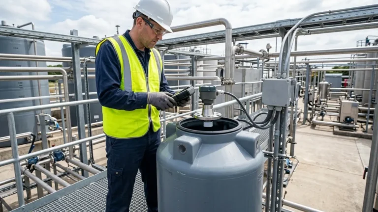
1 Ultrasonic Flow Meter
Understanding Ultrasonic Level Meters and Open-Channel Flow Measurement
In modern industrial automation, the ability to monitor liquid volumes and movement without physical contact is a significant advantage. Ultrasonic technology has emerged as a primary solution for these requirements, particularly in water treatment, chemical processing, and irrigation management. While often categorized separately, the relationship between level measurement and flow calculation is deeply integrated. A high-quality 1 ultrasonic flow meter configuration typically relies on the precision of Ultrasonic Level Meters to determine the "head" or height of a liquid in an open channel, which is then converted into a volumetric flow rate.
This guide explores the technical principles, selection criteria, and installation requirements for utilizing ultrasonic technology in industrial level and flow applications, providing engineers with a factual framework for system design.
Measurement Principles: From Level to Flow
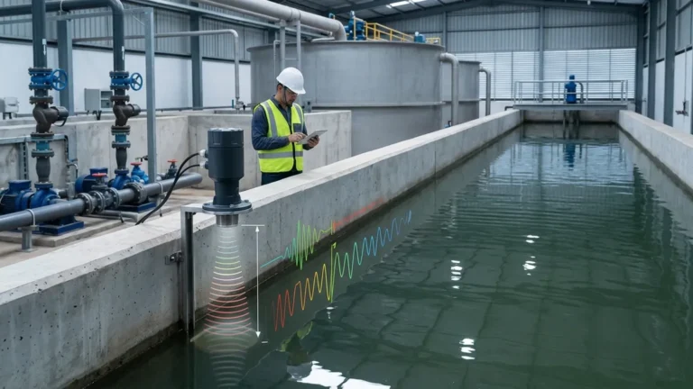
Before selecting equipment, it is essential to understand the physics of ultrasonic measurement. Ultrasonic sensors operate on the "Time of Flight" (ToF) principle. The transducer emits a high-frequency sound pulse—usually between 20 kHz and 75 kHz—which travels through the air, reflects off the surface of the liquid, and returns to the sensor.
The Level Calculation
The distance between the sensor and the liquid surface is calculated using the formula:
D = (c × t) / 2
Where:
* D is the distance.
* c is the speed of sound in the air (approximately 343 m/s at 20°C).
* t is the time elapsed between emission and reception.
By knowing the total height of the tank or the depth of the channel (H), the device calculates the liquid level (L) by subtracting the measured distance (D) from the total height (H).
The Flow Conversion
To function as a 1 ultrasonic flow meter in an open channel, the level meter must be paired with a primary device, such as a flume (e.g., Parshall, Palmer-Bowlus) or a weir (e.g., V-notch, rectangular). These structures have a known geometric relationship between the liquid level (head) and the flow rate. The ultrasonic transmitter is programmed with these specific curves (Q = h^n), allowing it to output real-time flow data in cubic meters per hour (m³/h) or liters per second (L/s).
Key Components of a 1 Ultrasonic Flow Meter System
A complete ultrasonic measurement setup generally consists of three main components:
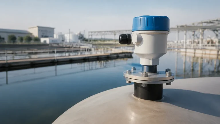
1. The Transducer (Sensor): This is the component that actually sends and receives the sound waves. In industrial environments, these are often made of PVDF or ETFE to resist chemical corrosion.
2. The Transmitter (Controller): This unit processes the signal, performs temperature compensation, and converts the time-of-flight data into level or flow units. It provides the user interface and output signals (4-20mA, RS485/Modbus, or HART).
3. The Primary Device (for Flow): As mentioned, this is the physical structure in the channel that creates a predictable relationship between level and velocity.
Welk provides integrated solutions where the transmitter includes pre-configured libraries for standard flumes and weirs, simplifying the setup for a 1 ultrasonic flow meter application.
Selection Criteria for Industrial Applications
Choosing the right instrument requires a detailed analysis of the process environment. Not all ultrasonic level meters are suitable for every application. Engineers should evaluate the following parameters:
1. Measurement Range
Ultrasonic sensors have a "blocking distance" or "dead zone" (typically 0.25m to 0.5m) directly beneath the transducer where they cannot measure. The maximum range must also exceed the deepest possible level of the tank or channel. Common industrial ranges vary from 5 meters (16.4 ft) to 15 meters (49.2 ft).
2. Beam Angle
The ultrasonic pulse spreads as it travels, forming a cone. A narrower beam angle (e.g., 5° to 10°) is preferable for narrow tanks or channels with internal obstructions like ladders or pipes, as it reduces the risk of false echoes.
3. Material Compatibility
For wastewater or acidic chemical tanks, the sensor face must be resistant to corrosion. Welk's range of ultrasonic level meters includes options with robust plastic housings designed for harsh industrial atmospheres.
4. Selection Table: Technical Comparison
| Feature | Compact Ultrasonic Meter | Remote/Split Ultrasonic Meter | High-Power Long Range |
| :— | :— | :— | :— |
| Typical Range | 0.4m – 10m | 0.4m – 15m | Up to 30m |
| Power Supply | 24V DC / 2-wire | 220V AC or 24V DC | 24V DC |
| Output | 4-20mA | 4-20mA, Relays, Modbus | 4-20mA, HART |
| Best Use Case | Standard tank level | Open channel flow | Large silos or deep sumps |
| Protection | IP67 | IP68 (Sensor) / IP65 (Transmitter) | IP66/IP67 |
Installation Best Practices for Accuracy
The accuracy of a 1 ultrasonic flow meter or level sensor is heavily dependent on proper installation. Even the most advanced sensor will fail if placed incorrectly.
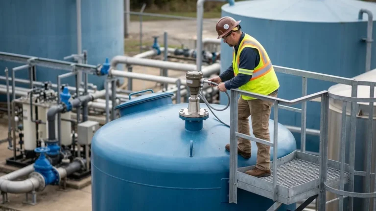
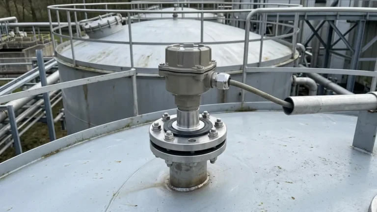
* Perpendicularity: The transducer must be mounted perfectly perpendicular to the liquid surface. A tilt of even a few degrees can cause the sound wave to reflect away from the sensor, leading to signal loss.
* Avoid the Inflow: Never mount the sensor directly above the point where liquid enters the tank or channel. Turbulence and air bubbles at the entry point will scatter the ultrasonic signal.
* Blocking Distance: Ensure the maximum liquid level never enters the sensor's dead zone. If the liquid reaches this zone, the meter will report an error or provide an erratic reading.
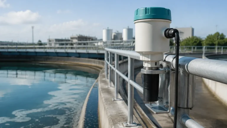
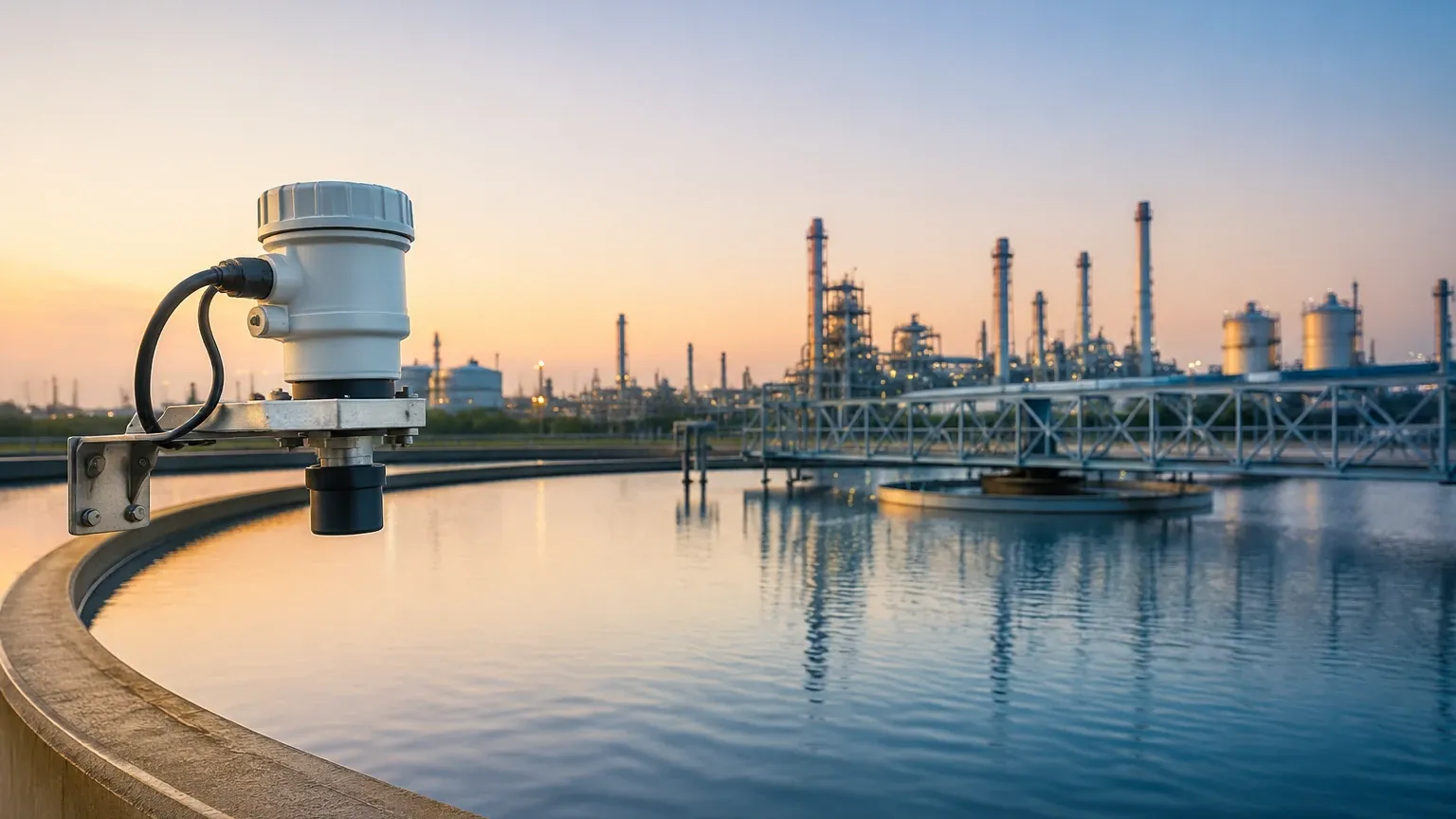
* Sun Shielding: In outdoor installations, direct sunlight can heat the sensor body, leading to inaccurate temperature compensation (since the speed of sound varies with air temperature). A simple sunshade is a critical addition for outdoor open-channel flow measurement.
* Stilling Wells: If the liquid surface is prone to heavy foam or extreme turbulence, a stilling well (a vertical pipe) can be used to provide a calm surface for the ultrasonic pulse to reflect from.
Limitations and Environmental Factors
While ultrasonic level meters are versatile, they are not universal solutions. Certain physical conditions can interfere with sound wave propagation:
1. Heavy Foam: Thick foam acts as an acoustic absorber. If the foam is dense enough, the ultrasonic pulse will not reflect back to the sensor, resulting in a "Lost Echo" error.
2. Dust and Vapor: High concentrations of dust (in dry bulk applications) or heavy steam/vapors can attenuate the signal. In these cases, radar level meters may be a more reliable alternative.
3. Vacuum and Pressure: Ultrasonic waves require a medium (air or gas) to travel. They cannot function in a vacuum. Furthermore, significant pressure changes can alter the density of the air, affecting the speed of sound and requiring specialized calibration.
4. Temperature Gradients: If there is a significant temperature difference between the sensor and the liquid surface, the speed of sound will change along the path. High-end meters use integrated temperature sensors to compensate for this, but extreme gradients can still introduce errors.
Maintenance and Troubleshooting FAQs
Q: Why is my meter showing a full tank when it is actually empty?
A: This is often caused by a "ringing" effect or a reflection from a nearby obstruction (like a pipe or wall) within the dead zone. Check the mounting position and ensure the beam path is clear.
Q: Can I use an ultrasonic level meter for solids?
A: Yes, but with caution. Solids like grain or plastic pellets often form a conical shape, which can deflect the sound wave. A higher-power sensor with a narrower beam is usually required for solids.
Q: How often does a 1 ultrasonic flow meter need calibration?
A: In stable environments, annual calibration is standard. However, if the primary device (flume/weir) accumulates debris or silt, the flow readings will become inaccurate regardless of the sensor's performance. Regular cleaning of the channel is essential.
Q: What is the difference between a 2-wire and 4-wire transmitter?
A: A 2-wire transmitter uses the same two wires for both power and the 4-20mA signal, which is more energy-efficient. A 4-wire transmitter has separate wires for power (often AC) and signal, allowing for higher power output and additional relays for pump control.
Conclusion for Engineering Teams
Integrating an ultrasonic level meter into your process provides a cost-effective, low-maintenance method for monitoring both storage levels and open-channel flow. By understanding the relationship between the sound wave's time-of-flight and the geometric requirements of flumes and weirs, engineers can successfully deploy a 1 ultrasonic flow meter system that delivers reliable data for years.
When specifying equipment, always prioritize the chemical compatibility of the transducer and the physical constraints of the installation site. For complex applications involving narrow spaces or potential foam, consulting with a specialist manufacturer like Welk ensures that the selected Ultrasonic Level Meters are optimized for the specific acoustic and environmental challenges of the facility.