Ultrasonic Level Sensor Installation
Ultrasonic Level Sensor Installation: A Comprehensive Engineering Guide
In the landscape of industrial automation, the accuracy of liquid and solid volume tracking depends heavily on the physical setup of the sensing equipment. Ultrasonic Level Meters have become a staple in water treatment, chemical processing, and oil and gas industries due to their non-contact nature and cost-effectiveness. However, the performance of these instruments is not solely determined by their internal circuitry; rather, it is significantly influenced by the environment and the precision of the ultrasonic level sensor installation.
This guide provides a technical deep-dive into the measurement principles, selection criteria, and rigorous installation protocols required to ensure reliable data in demanding industrial applications.
Understanding the Measurement Principle
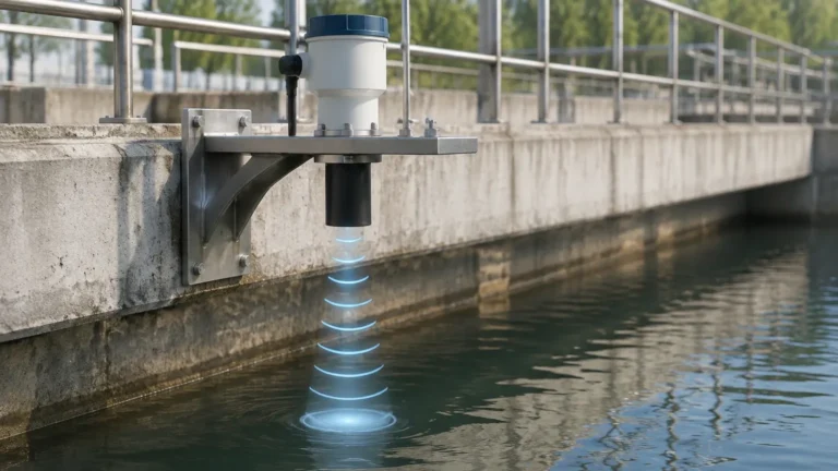
Before proceeding with installation, it is essential to understand the physics governing ultrasonic technology. Ultrasonic level sensors operate on the Time-of-Flight (ToF) principle. The sensor’s transducer emits high-frequency sound pulses (typically between 20 kHz and 200 kHz). These sound waves travel through the air, reflect off the surface of the medium (liquid or solid), and return to the transducer.
The distance ($D$) between the sensor and the material surface is calculated using the formula:
$$D = \frac{c \times t}{2}$$
Where:
- $c$ is the speed of sound in the medium (usually air).
- $t$ is the total time elapsed between transmission and reception.
Because the speed of sound is affected by air temperature (approximately 0.6 m/s change per degree Celsius), professional-grade Ultrasonic Level Meters from manufacturers like Welk incorporate integrated temperature sensors to compensate for these fluctuations automatically. Without proper compensation, a $10^\circ\text{C}$ shift could result in a measurement error of nearly 1.8%.
Pre-Installation Evaluation Criteria
Successful ultrasonic level sensor installation begins with a thorough site assessment. Engineers must confirm that the ultrasonic technology is compatible with the process conditions.
1. The "Dead Zone" or Blocking Distance
Every ultrasonic sensor has a minimum measurable distance, known as the "dead zone" or blocking distance. This is the area immediately in front of the transducer where the sensor cannot receive a return signal because it is still vibrating from the transmission pulse. If the liquid level enters this zone, the meter will provide erratic or maximum-level readings. Typically, this zone ranges from 0.2 meters to 0.8 meters (approx. 8 to 31 inches) depending on the sensor's frequency.
2. Beam Angle and Spread
The ultrasonic pulse does not travel in a straight line; it spreads out in a cone. The beam angle (usually between $5^\circ$ and $15^\circ$) determines the footprint of the signal at a specific depth. Any internal tank structures—such as ladders, heating coils, or agitators—that fall within this cone will cause "false echoes," leading to inaccurate level reporting.
3. Surface Characteristics
Ultrasonic waves require a reflective surface.
- Liquids: Generally provide excellent reflection unless they are covered in heavy foam, which absorbs sound waves.
- Solids: Granular materials like grain or plastic pellets have an "angle of repose" that can deflect the sound wave away from the transducer. In such cases, a swiveling mounting flange is often required to aim the sensor perpendicularly to the slope.
Step-by-Step Ultrasonic Level Sensor Installation Guide
Proper physical placement is the single most important factor in preventing signal loss. Follow these engineering guidelines for optimal results.
Positioning the Sensor
1. Avoid the Center: In cylindrical tanks with arched or conical roofs, do not mount the sensor in the exact center. The parabolic shape of the roof can focus multiple reflections back to the sensor, creating a "noise" effect that confuses the processor.
2. The 1/3 Radius Rule: A general rule of thumb for vertical cylindrical tanks is to install the sensor at approximately 1/3 to 1/2 of the tank radius away from the side wall.
3. Distance from the Wall: Ensure the sensor is not mounted too close to the tank wall. Smooth walls can cause signal attenuation, while rough walls or weld seams can create parasitic reflections. Maintain a minimum distance of at least 200mm (approx. 8 inches) from the wall for every 5 meters of tank height.
4. Avoid the Fill Stream: Never install the sensor directly above the inlet pipe. The falling liquid or solid will intercept the ultrasonic beam, causing the meter to read the level of the incoming stream rather than the tank contents.
Mounting and Alignment
- Perpendicularity: The transducer face must be perfectly parallel to the liquid surface. Even a $2^\circ$ or $3^\circ$ tilt can significantly reduce the strength of the return signal, especially at longer ranges.
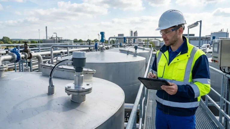
- Standpipe Usage: If a standpipe (nozzle) is used to mount the sensor, the inner diameter must be smooth and free of burrs. The transducer should ideally extend slightly beyond the bottom of the nozzle to prevent the "ringing" effect caused by the pipe walls. If the sensor must stay inside the nozzle, the nozzle should be as short and wide as possible.
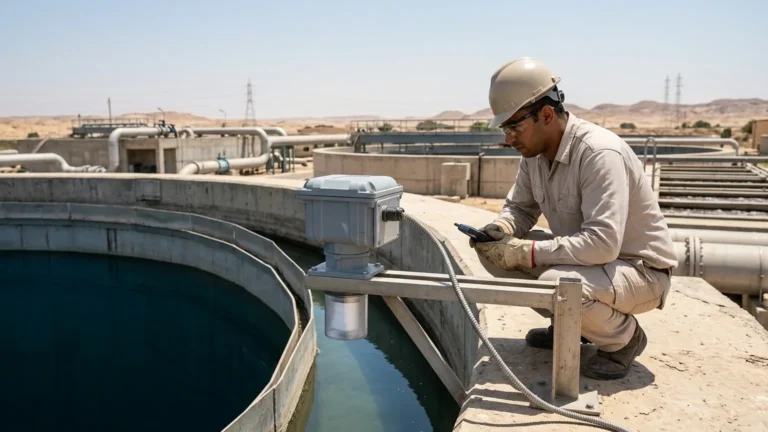
- Sun and Weather Protection: For outdoor installations, use a sunshade. Direct sunlight can heat the sensor body far above the actual ambient air temperature, leading to incorrect temperature compensation and measurement drift.
Electrical Wiring
Use shielded cables to prevent electromagnetic interference (EMI) from high-power equipment like pumps and variable frequency drives (VFDs). Ensure the cable entry points are sealed with proper glands to prevent moisture ingress (IP67/IP68 compliance), which is a leading cause of sensor failure in water treatment applications.
Practical Selection Table for Industrial Applications
When selecting a meter for your ultrasonic level sensor installation, use the following table to match the sensor specifications to your environment.
| Feature | Small Tank / Dosing | Standard Process Tank | Large Silo / Reservoir |
| :— | :— | :— | :— |
| Measurement Range | 0.2m – 5m | 0.4m – 15m | 0.8m – 30m |
| Frequency | High (60-80 kHz) | Medium (40-50 kHz) | Low (20-30 kHz) |
| Beam Angle | Narrow ($<6^\circ$) | Standard ($10^\circ$) | Wide ($15^\circ$) |
| Typical Accuracy | $\pm 2\text{mm}$ | $\pm 0.25\%$ of range | $\pm 0.5\%$ of range |
| Mounting | G1.5" or G2" Thread | Flange DN80/DN100 | Aiming Flange / Bracket |
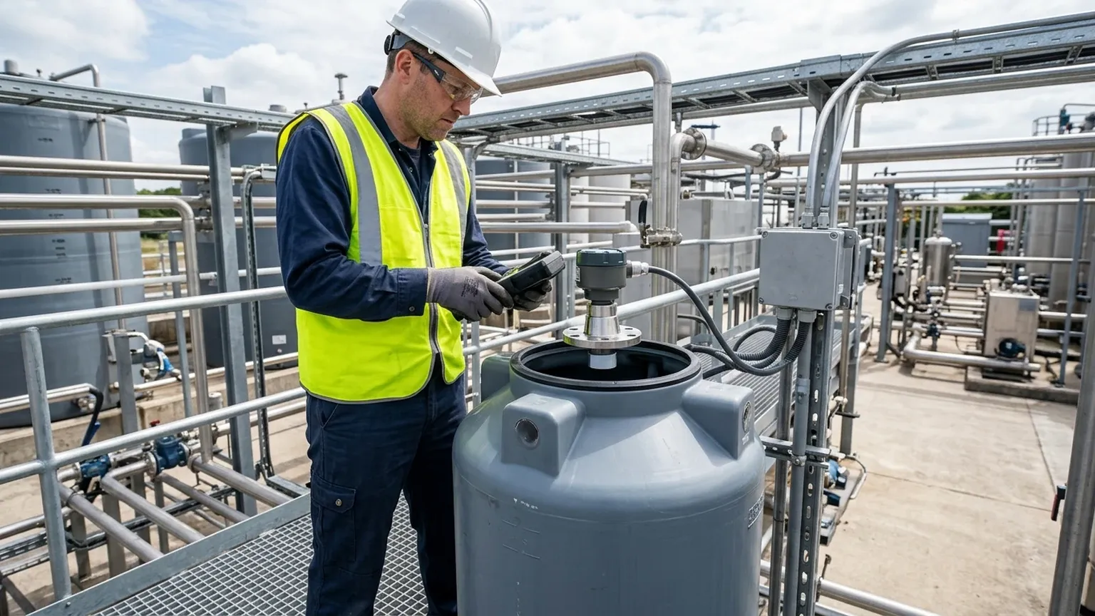
Limitations and Environmental Risks
While highly versatile, ultrasonic technology is not a "one-size-fits-all" solution. Engineers must be aware of the following limitations:
* Vacuum Conditions: Sound waves cannot travel in a vacuum. If the process involves a vacuum, radar level meters are the only viable non-contact alternative.
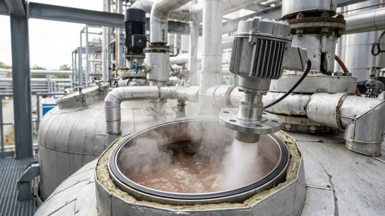
* Heavy Vapor and Steam: High concentrations of steam or chemical vapors can alter the density of the air, changing the speed of sound and causing significant errors. In these environments, high-frequency radar is often preferred.
* Acoustic Noise: Heavy machinery or pneumatic conveying systems can generate ultrasonic noise that interferes with the sensor's signal. Modern Welk sensors utilize digital filtering and "false echo suppression" software to mitigate this, but physical isolation is always better.
* Pressure Extremes: Most ultrasonic transducers are designed for atmospheric or near-atmospheric pressure (typically up to 3 bar). High-pressure applications can damage the transducer face or affect the wave propagation.
Troubleshooting Common Installation Issues (FAQ)
Q: Why does my sensor read "Full" when the tank is actually empty?
A: This is usually caused by the "Dead Zone" violation or a strong reflection from a nozzle or internal obstruction near the top of the tank. Check the mounting height and ensure the "Blocking Distance" parameter is set correctly in the software.
Q: The reading is stable when the agitator is off, but jumps when it is on. How do I fix this?
A: Agitators create turbulence and surface ripples that scatter the signal. You can increase the damping (averaging) time in the sensor settings or use a stilling well (a vertical pipe) to provide a calm surface for the measurement.
Q: Can I use an ultrasonic sensor for measuring the level of sulfuric acid?
A: Yes, provided the sensor body and transducer face are made of chemically resistant materials like PVDF or PTFE. Always check the chemical compatibility chart before installation.
Q: How do I handle foam on the liquid surface?
A: Light foam may be penetrated, but thick, dense foam will absorb the signal. If foam is a persistent issue, consider mounting the sensor inside a stilling well that extends below the foam layer, or switch to a hydrostatic level transmitter.
Conclusion
A successful ultrasonic level sensor installation requires a balance of theoretical understanding and practical site engineering. By respecting the physics of sound—accounting for beam angles, blocking distances, and temperature compensation—operators can achieve highly accurate, maintenance-free level monitoring. For critical applications, always consult the technical specifications of your specific Ultrasonic Level Meters to ensure the selected hardware meets the chemical and physical demands of your process.
Properly installed, these instruments provide the reliable data necessary for process safety, inventory management, and operational efficiency in the modern industrial environment.