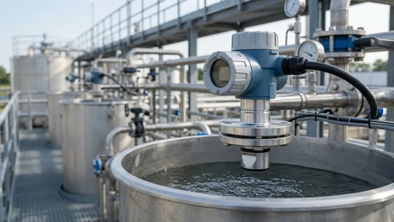
Ultrasonic Level Sensor Atex
Ultrasonic Level Sensor ATEX: Engineering Guide for Hazardous Environments
In industrial process control, monitoring liquid and solid levels in hazardous environments requires instrumentation that balances precision with rigorous safety compliance. The ultrasonic level sensor atex version is specifically engineered to operate in atmospheres where explosive gases, vapors, or dusts are present. By utilizing non-contact technology, these sensors eliminate many of the mechanical wear issues associated with traditional float or displacer systems, while their ATEX certification ensures they do not become an ignition source.
Selecting and implementing Ultrasonic Level Meters within explosive atmospheres involves understanding the intersection of acoustic physics and explosion protection standards. This guide provides a technical overview of measurement principles, ATEX classification, selection criteria, and installation best practices for engineering and maintenance professionals.
Measurement Principles of Ultrasonic Technology
Before evaluating specific ATEX-rated hardware, it is essential to understand how ultrasonic sensors derive level data. These instruments operate on the "Time of Flight" (ToF) principle.
The Transducer Mechanism
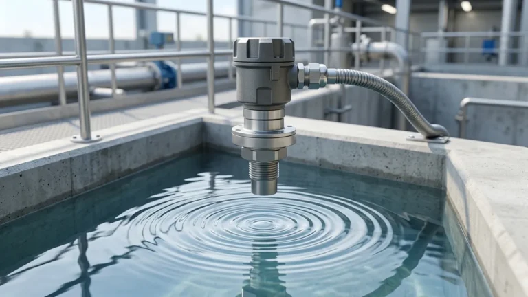
An ultrasonic sensor contains a piezoelectric crystal that acts as both a transmitter and a receiver. When excited by an electrical pulse, the crystal vibrates at a high frequency (typically between 20 kHz and 200 kHz), emitting an ultrasonic sound wave. This wave travels through the air or gas medium in the tank, reflects off the surface of the material, and returns to the transducer.
Distance Calculation
The sensor’s internal electronics measure the time interval between the emission of the pulse and the reception of the echo. The distance is calculated using the formula:
D = (v × t) / 2
Where:
* D is the distance to the material surface.
* v is the speed of sound in the medium (approximately 343 m/s in air at 20°C).
* t is the total time elapsed for the round trip.
By subtracting this distance from the known total height of the tank (the "zero point"), the device determines the actual level of the product.
Temperature Compensation
The speed of sound is highly dependent on the temperature of the medium through which it travels. For every 1°C change in temperature, the speed of sound changes by approximately 0.6 m/s. To maintain accuracy, a high-quality ultrasonic level sensor atex includes an integrated temperature sensor to automatically compensate for these variations in the vapor space.
Understanding ATEX Certification for Level Sensors
ATEX (Atmosphères Explosibles) refers to the European Union directives (2014/34/EU) that regulate equipment intended for use in potentially explosive atmospheres. For a level sensor to be utilized in such areas, it must undergo testing to ensure it cannot generate sparks or excessive heat.
ATEX Zones
Instruments are classified based on the frequency and duration of the occurrence of an explosive atmosphere:
* Zone 0 / Zone 20: Explosive atmosphere is present continuously or for long periods (e.g., inside a fuel tank).
* Zone 1 / Zone 21: Explosive atmosphere is likely to occur in normal operation occasionally.
* Zone 2 / Zone 22: Explosive atmosphere is not likely to occur in normal operation, but if it does, it will persist for a short period only.
Protection Methods
Most ATEX-certified ultrasonic sensors utilize one of two primary protection methods:
1. Intrinsic Safety (Ex i): The electrical energy within the circuit is limited to a level below that which could cause ignition by sparking or heating. These sensors must be used with an associated apparatus, such as a Zener barrier or galvanic isolator.
2. Flameproof/Explosion-Proof (Ex d): The housing is designed to contain any internal explosion and prevent it from igniting the surrounding atmosphere.
Practical Selection Criteria
When choosing an ultrasonic level sensor atex, engineers must look beyond the safety rating to ensure the device meets the physical requirements of the application.
Selection Table: ATEX vs. Standard Ultrasonic Sensors
| Feature | Standard Ultrasonic Meter | ATEX-Certified Ultrasonic Sensor |
| :— | :— | :— |
| Housing Material | Plastic or Aluminum | Reinforced Aluminum or Stainless Steel (316L) |
| Protection Rating | IP65/IP66 | IP66/IP67/IP68 |
| Certification | CE / General Purpose | ATEX, IECEx, or CSA/FM |
| Electrical Interface | Standard M12 or Terminal | ATEX-rated cable glands or conduits |
| Signal Output | 4-20mA, Modbus | 4-20mA HART (Intrinsically Safe) |
| Typical Application | Water storage, non-flammable bulk | Chemical reactors, fuel depots, wastewater wet wells |
Key Evaluation Factors
1. Measuring Range: Ensure the sensor’s range covers the full depth of the tank. Note that every sensor has a "blocking distance" (dead zone) directly beneath the transducer where measurement is impossible (typically 0.2m to 0.5m).
2. Chemical Compatibility: In hazardous environments, the vapor space often contains corrosive gases. The transducer face should be constructed from resistant materials like PVDF or PTFE.
3. Beam Angle: A narrower beam angle (e.g., 5° to 10°) is preferable for tanks with internal obstructions like ladders or agitators, as it reduces the risk of false echoes.
4. Process Pressure: Ultrasonic sensors generally operate best at atmospheric pressure. High pressure increases the density of the gas, which can affect sound propagation and accuracy.
Installation Considerations for Hazardous Areas
Proper installation is critical both for measurement accuracy and for maintaining the integrity of the ATEX protection.
Mechanical Mounting
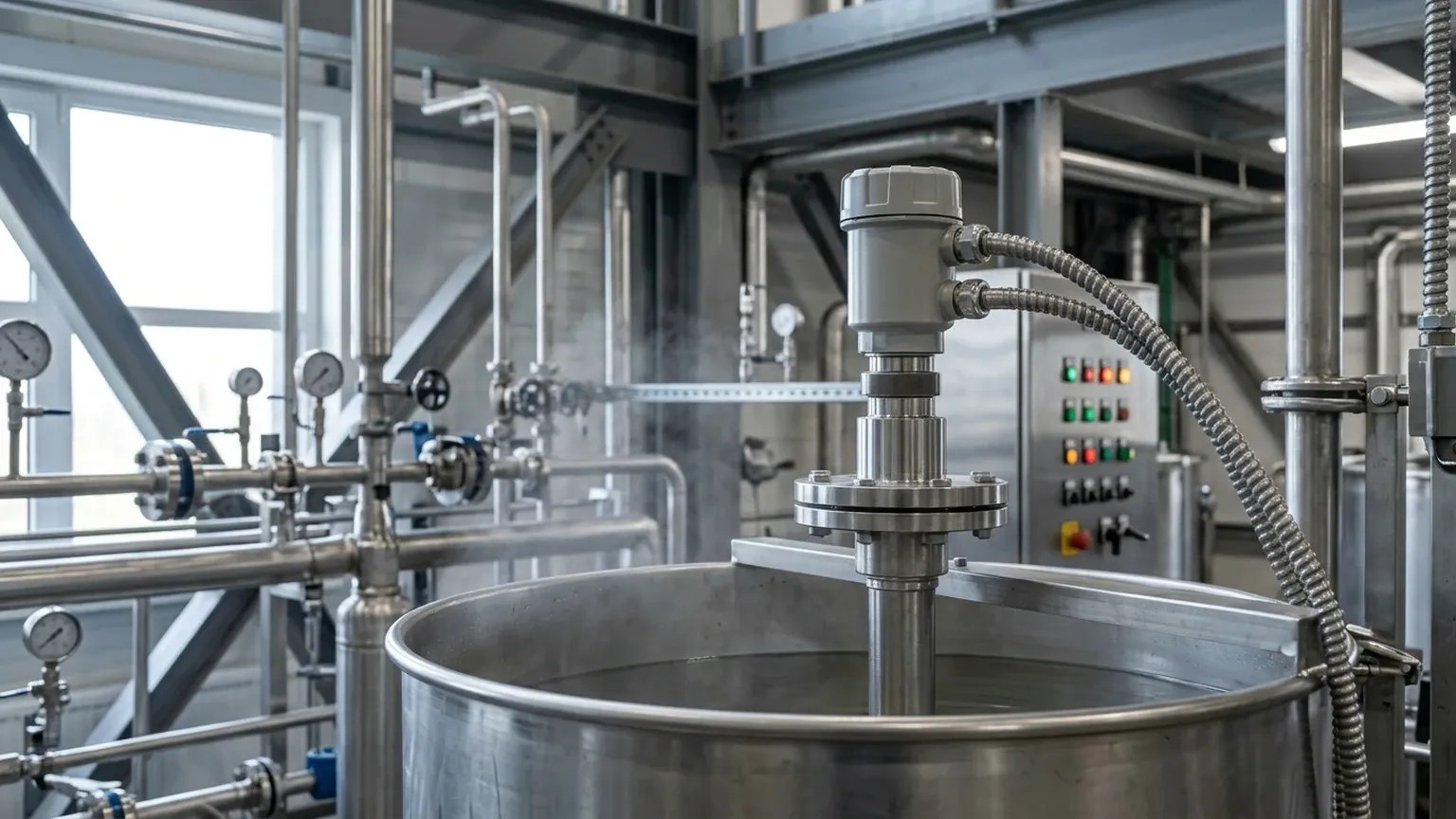
* Perpendicularity: The sensor must be mounted perfectly perpendicular to the liquid surface. A tilt of even a few degrees can cause the reflected signal to miss the receiver, leading to signal loss.
* Avoid the Fill Stream: Never mount the sensor directly above the inlet where falling material can interfere with the ultrasonic pulse.
* Nozzle Geometry: If mounting on a standpipe or nozzle, ensure the transducer face extends slightly beyond the bottom of the nozzle to prevent "ringing" or internal reflections within the pipe.
Electrical Installation
* Grounding: In ATEX environments, proper earthing is mandatory to prevent the buildup of static electricity.
* Cable Glands: Only use ATEX-certified cable glands that match the protection type (Ex d or Ex i) of the sensor.
* Separation of Cables: Intrinsically safe (IS) wiring must be physically separated from non-IS wiring in cable trays and control panels to prevent induction of dangerous voltages.
Limitations and Risks
While Ultrasonic Level Meters are versatile, they are not suitable for every hazardous application. Engineers should be aware of the following limitations:
* Heavy Foam: Foam on the surface of a liquid can absorb the ultrasonic signal, resulting in a "lost echo" error. In such cases, radar or hydrostatic sensors may be more appropriate.
* Vacuum Applications: Sound waves require a medium (gas) to travel. Ultrasonic sensors cannot function in a vacuum.
* Dust and Turbulence: While sensors can handle some dust, extremely heavy dust clouds in a silo can scatter the signal. Similarly, heavy surface turbulence can deflect the echo.
* Vapor Layers: Strong concentrations of solvent vapors (like toluene or ethanol) can change the speed of sound significantly compared to air. If the vapor concentration is not constant, temperature compensation alone may not be sufficient for high-accuracy requirements.
Maintenance and Safety Compliance
To ensure the ultrasonic level sensor atex remains safe throughout its lifecycle, a regular maintenance schedule is required.
1. Visual Inspection: Check for cracks in the housing or damage to the cable glands. In hazardous areas, even a small breach in a flameproof enclosure invalidates the safety rating.
2. Transducer Cleaning: In applications with condensing vapors or sticky materials, buildup on the transducer face can attenuate the signal. Clean the face with a soft cloth and compatible solvent.
3. Recalibration: Verify the accuracy against a manual dip-tape measurement annually. Ensure that the "Empty" and "Full" calibration points haven't drifted due to changes in the process environment.
Frequently Asked Questions (FAQs)
Q: Can I use a standard ultrasonic sensor in a Zone 2 area?
A: No. Only equipment specifically certified for ATEX Zone 2 (or higher) can be used. Using non-certified equipment in a hazardous area violates safety regulations and poses a significant explosion risk.
Q: What is the difference between ATEX and IECEx?
A: ATEX is a mandatory legal requirement for the European Union. IECEx is an international certification scheme. Many modern sensors carry both certifications to allow for global deployment.
Q: How does the beam angle affect the installation in small tanks?
A: In small or narrow tanks, a wide beam angle may hit the side walls, creating false echoes. A sensor with a narrow beam angle is necessary to ensure the pulse only reflects off the target material.
Q: Does the sensor work for solids like grain or plastic pellets?
A: Yes, but the range is typically reduced by about 50% because solids reflect sound less efficiently than liquids. Additionally, the angle of repose of the solid must be considered during mounting.
Conclusion
The implementation of an ultrasonic level sensor atex is a strategic choice for industries ranging from wastewater treatment to chemical processing. By understanding the acoustic principles and adhering to the strict installation requirements of hazardous area zones, facilities can achieve reliable, non-contact level monitoring. When selecting a device, always prioritize the specific ATEX zone requirements, chemical compatibility of the transducer, and the physical constraints of the vessel to ensure long-term operational success.