Q Sonic Ultrasonic Flow Meter Manual
Understanding Ultrasonic Measurement: From Level Monitoring to Flow Analysis
In the landscape of industrial process control, ultrasonic technology remains a cornerstone for non-contact measurement. Whether an engineer is tasked with monitoring the inventory of a chemical storage tank or calculating the volume of water moving through an open channel, the underlying physics of ultrasonic waves provide a versatile and cost-effective solution. This guide explores the principles of ultrasonic measurement, the critical distinctions between level and flow applications, and the technical considerations found in documentation such as the q sonic ultrasonic flow meter manual.
The Physics of Ultrasonic Measurement
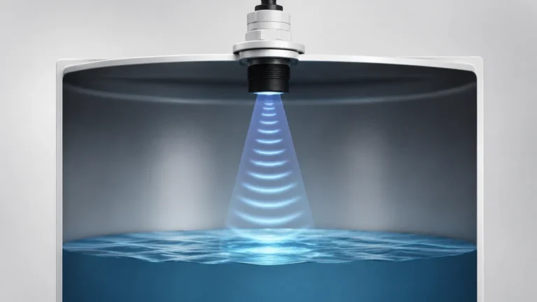
Ultrasonic measurement is based on the "Time-of-Flight" (ToF) principle. An ultrasonic transducer, typically utilizing piezoelectric crystals, converts electrical energy into high-frequency sound waves. These waves travel through the air (or the process medium) until they encounter a reflective surface—such as the top of a liquid or a solid material—and bounce back to the sensor.
The Calculation Formula
The distance between the sensor and the material surface is calculated using the speed of sound:
$$D = \frac{c \times t}{2}$$
Where:
* D is the distance to the surface.
* c is the speed of sound in the medium (approximately 343 m/s in air at 20°C).
* t is the total time elapsed from transmission to reception.
By knowing the total height of the vessel ($H$), the instrument calculates the actual level ($L$) by subtracting the measured distance from the total height ($L = H – D$). For industrial-grade Ultrasonic Level Meters, sophisticated algorithms are used to filter out "false echoes" caused by internal tank structures like ladders, agitators, or weld seams.
Ultrasonic Level vs. Flow: Key Distinctions
While the core technology relies on sound waves, the application of that technology differs significantly between level measurement and flow measurement.
1. Level Measurement (Time-of-Flight)
In level applications, the sensor is usually mounted at the top of a tank, pointing downward. The primary goal is to determine the vertical distance to the product surface. This is a "top-down" non-contact method ideal for corrosive, sticky, or abrasive liquids where mechanical contact would lead to sensor failure.
2. Flow Measurement (Transit-Time and Doppler)
Ultrasonic flow meters, such as those detailed in a q sonic ultrasonic flow meter manual, often use different methods:
* Transit-Time: Two transducers are used, one upstream and one downstream. Sound travels faster when moving with the flow and slower against it. The difference in time is proportional to the flow velocity.
* Doppler Effect: The sensor measures the frequency shift of sound waves reflecting off particles or bubbles in a moving liquid.
* Open Channel Flow: This is a hybrid application where an ultrasonic level meter measures the head (height) of water in a flume or weir and converts that height into a flow rate based on programmed hydraulic formulas.
Technical Insights from the Q Sonic Ultrasonic Flow Meter Manual
For high-precision gas or liquid flow measurement, the q sonic ultrasonic flow meter manual serves as a vital engineering reference. These manuals typically cover multi-path ultrasonic configurations, where multiple pairs of transducers are used to map the velocity profile across a pipe's cross-section.
Key areas addressed in such technical documentation include:
* Path Configuration: Detailed diagrams showing how the 3, 4, or 6 paths are aligned to compensate for swirl and non-axial flow.
* Signal Processing: Instructions on adjusting gain and threshold settings to ensure the meter can distinguish the ultrasonic pulse from background mechanical noise.
* Calibration Factors: Guidance on "Meter Factor" adjustments and Reynolds number corrections, which are essential for custody transfer applications.
* Maintenance Diagnostics: How to interpret signal-to-noise ratios (SNR) and "Acceptance Rates" to determine if the transducers require cleaning or if the process medium has changed.
Selection Criteria for Ultrasonic Instruments
Choosing the right instrument requires a balance between environmental factors and the physical properties of the material being measured. Use the following table as a preliminary selection guide for ultrasonic technology.
| Feature | Requirement / Specification |
| :— | :— |
| Measuring Range | Typically 0.1m to 30m (0.33ft to 98ft) depending on frequency. |
| Process Temperature | Generally limited to -40°C to +95°C (-40°F to 203°F). |
| Process Pressure | Best suited for atmospheric pressure; high pressure affects sound speed. |
| Accuracy | Standard ±0.25% of range; high-precision flow meters reach ±0.1%. |
| Beam Angle | Narrower angles (e.g., 5° to 10°) are better for narrow tanks. |
| Output Signals | 4-20mA, HART, Modbus RTU, or Profibus. |

Installation Best Practices for Accuracy
To ensure the reliability of the data, especially when following the rigorous standards set in a q sonic ultrasonic flow meter manual or a level meter installation guide, several physical factors must be managed.
1. The Blocking Distance (Dead Zone)
Every ultrasonic sensor has a "dead zone" directly in front of the transducer face where it cannot receive a return signal. If the liquid level rises into this zone, the meter will provide erratic readings. Always mount the sensor high enough to ensure the maximum liquid level never enters the blocking distance (typically 0.2m to 0.5m).
2. Perpendicular Alignment
The transducer face must be mounted perfectly parallel to the liquid surface. If the sensor is tilted, the sound wave will bounce off the surface at an angle and may not return to the receiver, resulting in a "Loss of Echo" (LOE) error.
3. Avoiding Obstructions
The ultrasonic beam spreads as it travels (the beam angle). Ensure there are no pipes, brackets, or agitator blades within the path of the cone. If obstructions are unavoidable, many modern Ultrasonic Level Meters allow for "False Echo Suppression," where the software is taught to ignore specific reflections at fixed distances.
4. Environmental Interference
* Wind and Turbulence: In outdoor open-channel flow applications, heavy wind can deflect the sound wave. Protective sunshades or stilling wells may be required.
* Vapor and Steam: Heavy steam or chemical vapors can change the density of the air, altering the speed of sound and introducing measurement errors. In these cases, temperature compensation is mandatory.
Limitations and Prohibitions
While ultrasonic meters are highly versatile, they are not universal solutions. Engineers should avoid using ultrasonic technology in the following scenarios:
* Vacuum Applications: Sound waves require a medium (air or gas) to travel. In a vacuum, ultrasonic measurement is impossible.
* Heavy Foam: Thick, protein-based foam absorbs sound waves rather than reflecting them. For foamy surfaces, radar level meters are generally preferred.
* High-Pressure Gases: In high-pressure environments, the change in gas density significantly impacts the speed of sound, requiring complex, real-time compensation that may exceed the capabilities of standard level meters.
Frequently Asked Questions (FAQ)
Q: How does temperature affect the accuracy of an ultrasonic meter?
A: The speed of sound changes by approximately 0.17% per degree Celsius. Most professional meters include an integrated temperature sensor to automatically compensate for these changes. However, if there is a significant temperature gradient between the sensor and the liquid surface, an external temperature probe may be necessary for higher accuracy.
Q: Can ultrasonic meters measure solids or powders?
A: Yes, but with caveats. Solids like grain or plastic pellets do not have a flat reflective surface; they form a cone. This scatters the sound signal. For solids, sensors with higher power and lower frequencies (to penetrate dust) are required, and the effective range is usually reduced by 50% compared to liquids.
Q: What is the difference between a 2-wire and 4-wire ultrasonic meter?
A: A 2-wire meter is loop-powered, meaning the power and the 4-20mA signal share the same pair of wires. These are easier to install but have less power for signal processing. A 4-wire meter has a separate power supply, providing more energy for the transducer to penetrate dust, steam, or long distances.
Q: Why is the q sonic ultrasonic flow meter manual so much more complex than a standard level meter manual?
A: Flow measurement in pipes involves fluid dynamics, Reynolds numbers, and velocity profiles. While a level meter simply measures distance, a flow meter like the Q Sonic must calculate volume over time across a dynamic environment, requiring more detailed calibration and configuration steps.
Conclusion
Ultrasonic technology offers a robust, non-contact method for managing both inventory levels and flow rates across various industries. By understanding the fundamental principles of sound propagation and adhering to the technical guidelines found in resources like the q sonic ultrasonic flow meter manual, plant operators can achieve high levels of precision and reliability. Whether you are implementing a simple tank level alert or a complex flow monitoring system, proper selection and installation remain the keys to long-term success.