Ultrasonic Point Level Measurement
Ultrasonic Point Level Measurement: A Practical Engineering Guide
In the landscape of industrial process automation, level measurement is categorized into two primary functions: continuous measurement and point level detection. While continuous measurement provides a real-time tracking of the fluid surface throughout the vessel's height, ultrasonic point level measurement serves as a critical safeguard, identifying when a substance reaches a specific, predetermined height. This functionality is essential for overfill protection, dry-run prevention for pumps, and high/low-level alarming in storage tanks and process vessels.
For engineers and plant managers, choosing the correct technology requires a deep understanding of acoustic physics, media characteristics, and environmental constraints. This guide explores the principles, applications, and selection criteria for implementing ultrasonic solutions in point level detection scenarios.
Understanding Ultrasonic Point Level Measurement Principles
Ultrasonic technology relies on the transmission and reflection of high-frequency sound waves, typically above the range of human hearing (20 kHz to 200 kHz). In the context of point level detection, two distinct methods are commonly employed: non-contact time-of-flight (ToF) and contact-based gap sensing.
Non-Contact Time-of-Flight
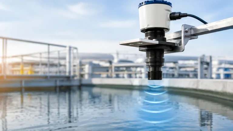
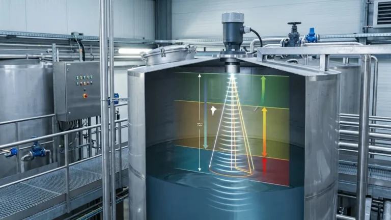
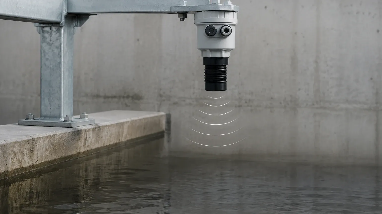
Most modern Ultrasonic Level Meters utilize the non-contact method. The sensor’s transducer acts as both a transmitter and a receiver. It emits a pulse of sound that travels through the air (or vapor space), reflects off the surface of the material, and returns to the transducer.
The distance is calculated using the formula:
Distance = (Speed of Sound × Time) / 2
For point level applications, the device is configured with specific switching thresholds. When the calculated distance matches the programmed setpoint, an internal relay or digital output is triggered. This method is preferred when the media is corrosive, viscous, or if hygiene requirements dictate that the sensor should not touch the process material.
Ultrasonic Gap Sensors (Contact Method)
Dedicated ultrasonic point level switches often use a "gap" principle. These sensors consist of two piezoelectric crystals separated by a small physical gap. One crystal transmits a continuous ultrasonic signal, and the other acts as a receiver.
* In Air: When the gap is filled with air or gas, the ultrasonic signal is highly attenuated and cannot reach the receiver.
* In Liquid: When liquid enters the gap, it acts as an efficient medium for sound transmission. The receiver detects the signal, and the electronics trigger a state change (e.g., from "off" to "on").
Key Components and System Architecture
A robust ultrasonic point level system consists of three primary elements:
1. The Transducer: The "heart" of the instrument, containing piezoelectric crystals that convert electrical energy into mechanical vibrations (sound) and vice versa. Materials like PVDF or PTFE are often used for the transducer face to ensure chemical compatibility.
2. The Electronic Controller: This unit processes the signal, filters out noise, and performs temperature compensation. In many Ultrasonic Level Meters, the controller includes advanced algorithms for "False Echo Suppression," which ignores reflections from internal tank structures like ladders or agitators.
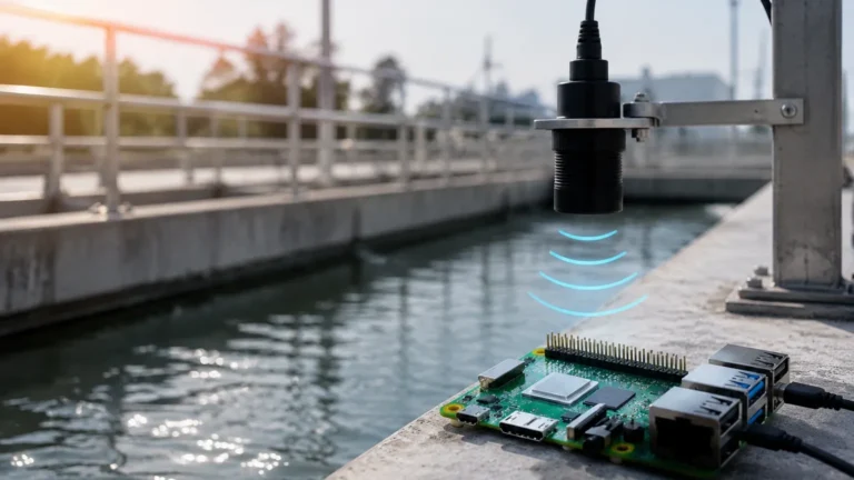
3. The Output Interface: For point level detection, this is typically a relay (SPDT/DPDT), a PNP/NPN transistor switch, or a digital protocol like HART or Modbus that communicates the alarm status to a PLC or SCADA system.
Industrial Applications and Use Cases
Ultrasonic point level measurement is versatile across various sectors, particularly where contact-based mechanical floats might fail due to buildup or mechanical fatigue.
Water and Wastewater Treatment
In wet wells and lift stations, ultrasonic sensors are used to trigger pumps. A high-level setpoint starts the pump, while a low-level setpoint stops it to prevent cavitation and dry-running. Because the measurement is non-contact, the sensors are unaffected by the debris and grease common in sewage.
Chemical Processing
For aggressive acids or bases, non-contact ultrasonic measurement prevents sensor degradation. Point level switches are often installed as redundant safety systems (High-High Alarms) to prevent catastrophic overfills in bulk storage tanks.
Food and Beverage
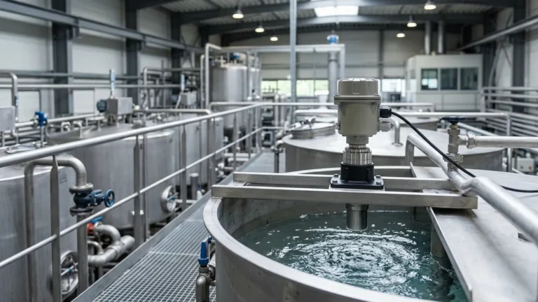
In applications requiring CIP (Clean-in-Place) or SIP (Steam-in-Place) cycles, ultrasonic gap sensors or non-contact meters with sanitary fittings (such as Tri-Clamp) provide reliable detection without creating stagnant zones where bacteria could grow.
Selection Criteria: Choosing the Right Ultrasonic Solution
Selecting the appropriate instrument requires balancing technical specifications with the physical realities of the installation site. The following table provides a baseline for evaluating ultrasonic technology against common process variables.
Selection Matrix for Ultrasonic Level Measurement
| Variable | Suitability | Engineering Consideration |
| :— | :— | :— |
| Liquid (Clean) | Excellent | Ideal for water, oils, and chemicals. |
| Liquid (Slurries) | Good | Non-contact prevents clogging; check for heavy surface foam. |
| Solids/Powders | Fair | Signal may scatter; requires high-power transducers and specific aiming. |
| Pressure | Limited | Typically rated for atmospheric to 3 bar (43.5 psi). |
| Temperature | Moderate | Standard range is -40°C to 80°C (-40°F to 176°F). |
| Vacuum | Poor | Sound cannot travel in a vacuum; requires a medium (air/gas). |
Media Characteristics
When implementing ultrasonic point level measurement, the density and viscosity of the liquid are generally less important than its surface state. A calm, reflective surface is ideal. If the media is prone to heavy foaming, the foam can absorb the ultrasonic pulse, leading to a "Loss of Echo" (LOE) error. In such cases, a different technology, like a magnetic level gauge or a radar transmitter, may be more appropriate.
Installation Guidelines and Best Practices
Proper installation is the most significant factor in the reliability of an ultrasonic system. Even the most advanced Ultrasonic Level Meters will fail if acoustic principles are ignored during mounting.
1. The Blocking Distance (Dead Zone): Every ultrasonic transducer has a "dead zone" near the sensor face where it cannot receive an echo because it is still vibrating from the transmission. Ensure the maximum liquid level never enters this zone (typically 0.2m to 0.5m depending on the model).
2. Perpendicular Alignment: The transducer face must be mounted perfectly parallel to the liquid surface. A deviation of just a few degrees can cause the reflected signal to bounce away from the receiver, especially at longer ranges.
3. Beam Angle and Obstructions: Ultrasonic pulses spread out in a cone (usually 5° to 12°). The "keep-out" zone must be free of pipes, ladders, or internal baffles. If an obstruction is unavoidable, use a device with software-based false echo mapping.
4. Avoid the Fill Stream: Never mount the sensor directly above the point where liquid enters the tank. The turbulence and entrained air will scatter the signal and cause erratic readings.
5. Standpipe Mounting: If the tank has a narrow nozzle, a standpipe (still-well) can be used to guide the signal and eliminate surface turbulence. However, the pipe's interior must be smooth and free of burrs or joints.
Technical Limitations and Environmental Factors
While highly effective, ultrasonic technology has physical boundaries that engineers must respect to avoid false alarms or system failures.
* Atmospheric Composition: The speed of sound is affected by the gas through which it travels. If the vapor space is filled with heavy vapors (like certain hydrocarbons) instead of air, the distance calculation will be inaccurate unless the sensor is calibrated for that specific gas constant.
* Temperature Gradients: Rapid temperature changes or significant gradients between the liquid and the sensor can cause the sound wave to refract (bend). Integrated temperature sensors in the transducer help mitigate this, but they only measure the temperature at the sensor, not the entire path.
* Acoustic Noise: High-frequency noise from nearby machinery or pneumatic conveying systems can interfere with the ultrasonic signal. Modern digital filtering helps, but physical isolation is always preferred.
* Vapor and Condensation: While light condensation on the transducer face is often manageable, heavy droplets can attenuate the signal. Some transducers feature a self-cleaning or "drip-off" design to shed moisture.
Frequently Asked Questions (FAQ)
Q: Can ultrasonic point level measurement be used in pressurized tanks?
A: Most ultrasonic sensors are designed for atmospheric or low-pressure applications (up to 3 bar). High pressure increases the density of the gas, which can change the speed of sound and affect the transducer's ability to vibrate efficiently.
Q: How does foam affect the measurement?
A: It depends on the foam's density. Light, airy foam might allow the signal to pass through to the liquid, whereas thick, dense foam (like shaving cream) will absorb the signal entirely. In high-foam applications, contact-based ultrasonic gap switches or radar are often better choices.
Q: Is it possible to use one ultrasonic meter for multiple point levels?
A: Yes. Many Ultrasonic Level Meters include multiple programmable relays. You can set one for "High Alarm," one for "Low Alarm," and use the 4-20mA output for continuous monitoring.
Q: What maintenance is required?
A: Ultrasonic sensors are generally low-maintenance because they have no moving parts. Periodic inspection of the transducer face for buildup or heavy condensation is recommended. If buildup occurs, it should be cleaned with a soft cloth and a compatible solvent.
Conclusion
Ultrasonic point level measurement remains a cornerstone of industrial instrumentation due to its cost-effectiveness, ease of installation, and non-contact nature. By carefully considering the acoustic environment and the physical properties of the process media, engineers can implement highly reliable level detection systems that enhance plant safety and operational efficiency. When applications exceed the limits of ultrasonic technology—such as in high-pressure steam or vacuum environments—consulting with a professional manufacturer like Welk can help identify alternative solutions like radar or magnetic level gauges to ensure process integrity.