Ultrasonic Length Measurement
Ultrasonic Length Measurement: A Technical Guide for Industrial Applications
In the landscape of industrial automation and process control, the ability to determine distances accurately without physical contact is a fundamental requirement. Ultrasonic length measurement has emerged as a cornerstone technology for this purpose, providing a reliable, cost-effective, and versatile solution for monitoring everything from material levels in silos to the dimensions of objects on a production line.
As a professional manufacturer, Welk specializes in integrating these principles into high-performance Ultrasonic Level Meters, ensuring that engineers and plant managers can maintain precise control over their inventory and processes. This guide explores the physics, application engineering, and selection criteria necessary for implementing ultrasonic technology in demanding industrial environments.
Understanding the Measurement Principle
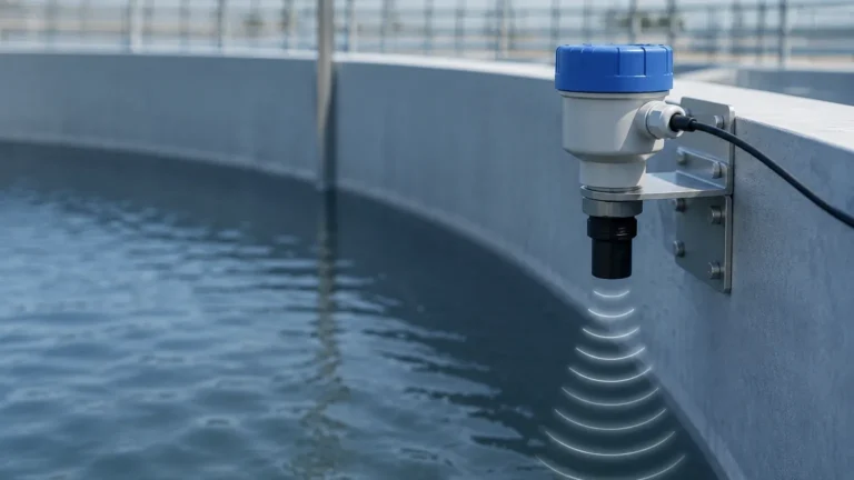
Ultrasonic length measurement relies on the propagation of high-frequency sound waves—typically above the range of human hearing (20 kHz to 200 kHz). The process is governed by the Time-of-Flight (ToF) principle, which measures the duration between the emission of a pulse and the reception of its echo.
The Time-of-Flight (ToF) Calculation
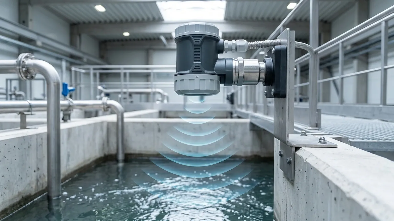
An ultrasonic transducer acts as both a transmitter and a receiver. It emits a short burst of sound waves toward a target. When these waves hit the surface of the target, they reflect back toward the sensor. The internal electronics of the transmitter record the time elapsed ($t$). The distance ($D$) is then calculated using the following formula:
$$D = \frac{v \times t}{2}$$
Where:
* $D$ is the distance (or length) from the sensor to the target.
* $v$ is the speed of sound in the medium (usually air).
* $t$ is the total travel time of the pulse.
Because the pulse must travel to the target and back, the product of velocity and time is divided by two to determine the one-way distance.
The Role of Temperature Compensation
The speed of sound is not a constant; it is significantly influenced by the temperature of the medium through which it travels. In air at sea level, the speed of sound ($v$) can be approximated by:
$$v \approx 331.5 + 0.6 \times T$$
Where $T$ is the temperature in degrees Celsius (°C). A change of just 10°C can result in a measurement error of approximately 1.8% if not corrected. Professional-grade ultrasonic length measurement systems, such as those produced by Welk, incorporate integrated temperature sensors to provide real-time compensation, ensuring accuracy remains within specified tolerances despite fluctuating ambient conditions.
Key Components of an Ultrasonic System
To achieve reliable ultrasonic length measurement in an industrial setting, several components must work in harmony:
1. The Transducer: The heart of the device, often utilizing piezoelectric crystals. When energized with electricity, the crystal vibrates to create sound waves (the converse piezoelectric effect). When the echo returns, the vibration of the crystal generates an electrical signal.
2. Signal Processing Electronics: Industrial environments are noisy. Advanced electronics are required to filter out "false echoes" caused by tank agitators, structural supports, or acoustic noise from machinery.
3. The Housing: For B2B applications, the housing must often meet specific ingress protection ratings (e.g., IP66, IP67, or IP68) and be resistant to corrosive chemicals or explosive atmospheres (ATEX/IECEx).
Practical Selection Criteria
When selecting an instrument for ultrasonic length measurement, engineers must balance technical requirements with environmental constraints. The following table provides a general framework for evaluating these instruments.
Selection Table: Technical Specifications
| Feature | Standard Industrial Range | High-Precision Applications |
| :— | :— | :— |
| Measuring Range | 0.3 m to 15 m | 0.1 m to 5 m |
| Accuracy | ±0.5% of full scale | ±0.2% of full scale |
| Resolution | 1 mm to 3 mm | < 1 mm |
| Beam Angle | 8° to 12° | 3° to 6° |
| Output Signals | 4-20mA, RS485, Modbus | 4-20mA, HART, Profibus |
| Operating Pressure| Atmospheric (±0.5 bar) | Atmospheric |
| Operating Temp | -40°C to +70°C | -20°C to +60°C |
Frequency vs. Range
There is an inverse relationship between the frequency of the ultrasonic pulse and the maximum measurable distance. Higher frequencies (e.g., 100 kHz+) provide better resolution and are less susceptible to background noise but attenuate quickly in the air, limiting their range. Conversely, lower frequencies (e.g., 20 kHz to 40 kHz) can travel much further—up to 30 or 40 meters—but require larger transducers and have wider beam angles.
Installation Guidelines and Best Practices
The performance of an ultrasonic length measurement system is heavily dependent on proper installation. Even the most advanced sensor will fail if placed incorrectly.
1. The "Dead Zone" (Blocking Distance)
Every ultrasonic sensor has a "dead zone" immediately in front of the transducer face where it cannot accurately process an echo. This occurs because the transducer needs a few milliseconds to stop vibrating after transmitting before it can listen for a return signal. Typical dead zones range from 0.2 m to 0.5 m. The sensor must be mounted high enough so that the target never enters this zone.
2. Beam Angle and Obstructions
The ultrasonic pulse spreads out in a cone shape. Any object that enters this cone—such as a ladder, a pipe, or a reinforcement beam—will create a reflection. If these reflections are stronger than the reflection from the actual target, the device will report an incorrect distance.
* Rule of Thumb: Ensure the path is clear of obstructions within a 10° radius of the sensor's center axis.
* Mounting Position: In tank level applications, avoid mounting the sensor in the exact center of a domed tank, as this can focus unwanted secondary echoes. Ideally, mount the sensor at 1/3 the radius from the tank wall.
3. Surface Characteristics
Ultrasonic waves reflect best off hard, flat surfaces. If the target is a liquid, the surface should be relatively calm. If the target is a solid (like grain or plastic pellets), the angle of repose can deflect the sound wave away from the sensor. In such cases, a sensor with a higher power output or a swivel mounting flange may be required to align the sensor with the material surface.
Limitations of Ultrasonic Technology
While highly versatile, ultrasonic length measurement is not a universal solution. Engineers should be aware of the following limitations:
* Vacuum Conditions: Sound requires a medium (gas) to travel. Ultrasonic sensors will not function in a vacuum.
* High Pressure/Heavy Vapor: High-pressure environments change the density of the air, affecting sound propagation. Similarly, heavy steam or chemical vapors can absorb the sound energy or change the speed of sound unpredictably.
* Heavy Foam: In liquid level sensing, thick foam can act as an acoustic insulator, absorbing the pulse rather than reflecting it. In these instances, a hydrostatic pressure transmitter or a radar level meter may be more appropriate.
* Extreme Temperatures: While compensation exists, temperatures exceeding 80°C can damage standard piezoelectric crystals and significantly degrade measurement accuracy.
Comparison: Ultrasonic vs. Radar and Laser
In many B2B procurement scenarios, the choice often falls between ultrasonic, radar, and laser measurement.
* Ultrasonic: Best for general-purpose applications, non-contact requirements, and budget-conscious projects. It is unaffected by the dielectric constant of the material.
* Radar (Microwave): Superior for high-pressure, high-temperature, or vacuum applications. Radar waves are not affected by air temperature or dust, but they are more expensive.
* Laser: Offers the highest precision and the narrowest beam, but can be hindered by dust, steam, or transparent surfaces.
Frequently Asked Questions (FAQ)
Q: Can ultrasonic sensors measure the length of transparent objects?
A: Yes. Unlike optical or laser sensors, ultrasonic waves reflect off the physical density of the object, making them ideal for clear glass, plastic films, or water.
Q: How does dust affect ultrasonic length measurement?
A: Moderate dust generally does not interfere with the low-frequency sound waves used in industrial sensors. However, extremely heavy dust can attenuate the signal. Regular cleaning of the transducer face is recommended in these environments.
Q: What is the typical lifespan of a Welk ultrasonic sensor?
A: With no moving parts and non-contact operation, these sensors typically last 7 to 10 years in standard industrial environments, provided they are operated within their temperature and chemical compatibility limits.
Q: How do I handle signal loss due to turbulence?
A: For turbulent liquids, software dampening (averaging the signal) or the use of a stilling well can stabilize the measurement. Welk Ultrasonic Level Meters include programmable filters to handle such process fluctuations.
Conclusion
Ultrasonic length measurement remains a primary choice for industrial distance and level sensing due to its balance of accuracy and cost-effectiveness. By understanding the underlying physics—specifically the impact of temperature and the necessity of a clear path for the acoustic beam—engineers can implement robust systems that enhance operational efficiency. Whether monitoring bulk solids or liquid chemicals, selecting the right frequency and ensuring proper installation are the keys to long-term success in process automation.