Ultrasonic Level Measurement and Control Quizlet
Ultrasonic Level Measurement and Control: A Comprehensive Engineering Guide
In the field of industrial automation, mastering the principles of non-contact sensing is essential for efficient process management. Many engineering students and junior technicians often search for resources like an "ultrasonic level measurement and control quizlet" to grasp the fundamental logic of these systems. However, moving from academic theory to field application requires a deep understanding of how Ultrasonic Level Meters interact with various environments, materials, and control architectures.
This guide serves as a practical reference for choosing, installing, and maintaining ultrasonic level measurement systems in B2B environments, ranging from water treatment plants to chemical processing facilities.
1. The Principle of Ultrasonic Level Measurement
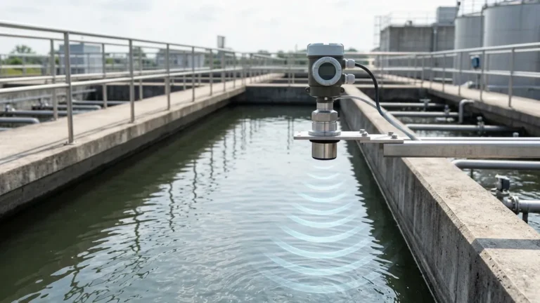
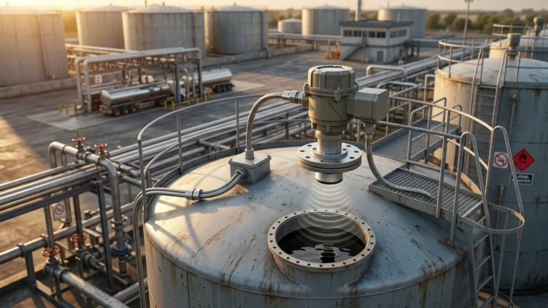
Ultrasonic level measurement is based on the "Time of Flight" (ToF) principle. The instrument’s transducer emits high-frequency sound pulses—typically between 20 kHz and 200 kHz—which travel through the air toward the surface of the medium being measured. When the sound waves hit the surface, they are reflected back as an echo to the transducer.
The Mathematical Foundation
The distance from the transducer to the material surface is calculated using the following formula:
Distance = (Speed of Sound × Time Delay) / 2
Since the speed of sound in air is approximately 344 m/s (1,128 ft/s) at 20°C (68°F), the transmitter can precisely determine the distance by measuring the micro-intervals of time between the pulse emission and the echo reception. To determine the actual level of the liquid or solid in a tank, the device subtracts the measured distance from the total tank height (the calibration distance).
The Role of Temperature Compensation
One of the most critical factors in ultrasonic measurement is temperature. The speed of sound changes by approximately 0.17% per degree Celsius. Therefore, professional-grade ultrasonic level meters include an integrated temperature sensor to provide real-time compensation, ensuring accuracy remains within the standard ±0.2% to ±0.5% range even as ambient or process temperatures fluctuate.
2. Integration into Control Systems
Measurement is only the first step; the "control" aspect involves translating that distance data into actionable signals for industrial automation. When reviewing an ultrasonic level measurement and control quizlet, the focus is often on how these signals interface with a Programmable Logic Controller (PLC) or Distributed Control System (DCS).
Signal Outputs
Modern ultrasonic transmitters typically offer several output options:
* 4-20mA Analog Output: The industry standard for continuous level monitoring, where 4mA represents an empty tank and 20mA represents a full tank.
* HART Protocol: Allows for digital communication over the analog wiring, enabling remote diagnostics and configuration.
* Modbus RTU (RS485): Ideal for networking multiple sensors over long distances to a central control hub.
* Relay Switches: Used for direct pump control (Start/Stop) or high/low-level alarms.
Logic and Programming
Control logic often includes "damping" or "averaging" filters. These software algorithms prevent erratic readings caused by surface turbulence or occasional splashing, ensuring the control system does not cycle pumps on and off too rapidly (chatter).
3. Practical Selection Criteria
Selecting the right instrument requires matching the sensor's frequency and power to the specific application requirements. Lower frequency sensors (e.g., 20 kHz) have longer ranges and better penetration through dust or steam, while higher frequency sensors (e.g., 60 kHz+) offer higher resolution for short-range, precision measurements.
Selection Table: Ultrasonic vs. Application Needs
| Feature | Specification / Requirement | Engineering Consideration |
| :— | :— | :— |
| Measurement Range | 0.3m to 30m (1ft to 98ft) | Choose a sensor with a range 20% greater than the tank height. |
| Beam Angle | 5° to 12° | Narrower beams are better for narrow tanks with internal obstructions. |
| Process Temperature | -40°C to +80°C | Ensure the transducer material (PVDF/PP) is compatible. |
| Output Type | 2-wire or 4-wire | 2-wire is loop-powered; 4-wire allows for higher power/relays. |
| Accuracy | ±0.25% of full scale | Suitable for most inventory and process control tasks. |
4. Installation Best Practices
Even the most advanced Ultrasonic Level Meters will fail if installed incorrectly. Field engineers must adhere to specific geometry and environmental rules to ensure a reliable signal.
The Blocking Distance (Dead Zone)
Every ultrasonic sensor has a "dead zone" directly beneath the transducer face where it cannot measure. This is caused by the time required for the transducer to stop vibrating (ringing) after emitting a pulse before it can listen for the return echo. If the liquid level enters this zone, the meter will provide an error or a false reading. Always mount the sensor high enough so the maximum liquid level stays below the blocking distance (typically 0.2m to 0.5m).
Avoiding Obstructions
The ultrasonic pulse spreads out in a cone shape. Any internal tank structures—such as ladders, heating coils, or agitators—that fall within this beam angle will create "false echoes."
* Solution: Mount the sensor away from the tank wall (at least 1/6th of the tank diameter) and away from the fill inlet to avoid interference from falling liquid.
* False Echo Suppression: Modern Welk instruments allow users to "map" the tank, telling the software to ignore specific static echoes at known distances.
Surface Conditions
Ultrasonic waves reflect best off flat, hard surfaces.
* Turbulence: Heavy ripples can scatter the sound waves. Using a stilling well (a pipe that extends into the liquid) can provide a calm surface for the measurement.
* Foam: Soft, light foam absorbs ultrasonic energy, often resulting in a "Lost Echo" error. For heavy foam applications, radar technology or hydrostatic pressure sensors may be more appropriate.
5. Limitations and Prohibitions
While ultrasonic technology is versatile and cost-effective, it is not a universal solution. Engineers must recognize the physical boundaries of sound-based measurement.
1. Vacuum Applications: Sound waves require a medium (air or gas) to travel. In a vacuum, ultrasonic meters cannot function.
2. High Pressure: As pressure increases, the density of the gas changes, which can affect the transducer's ability to couple with the air, potentially reducing signal strength.
3. Heavy Vapor/Steam: Dense vapors or steam can change the speed of sound significantly or attenuate the signal, leading to inaccuracies.
4. Dusty Solids: While ultrasonic meters can measure solids, fine dust can absorb the sound pulse. High-power, low-frequency sensors are required for these environments.
6. Maintenance and Troubleshooting
Ultrasonic meters are generally low-maintenance because they have no moving parts and do not touch the process media. However, periodic checks are recommended.
* Transducer Face Cleaning: In humid or dusty environments, condensation or buildup can occur on the transducer face. A gentle wipe with a soft cloth is usually sufficient.
* Signal Strength Diagnostics: Most digital transmitters provide a "Signal-to-Noise Ratio" (SNR). A declining SNR over time may indicate transducer degradation or increasing environmental interference.
* Recalibration: While the electronics do not drift, changes in the gas composition (e.g., a shift from air to a CO2-rich environment) will change the speed of sound and require a new calibration factor.
7. Knowledge Check: Professional "Quizlet" Review
To bridge the gap between academic study and professional practice, here are the core concepts often found in an ultrasonic level measurement and control quizlet, answered with engineering precision:
Q: What happens to the level reading if the ambient temperature increases but the sensor has no compensation?
A: The speed of sound increases with temperature. Without compensation, the meter would calculate a shorter time of flight, making the distance appear smaller and the liquid level appear higher than it actually is.
Q: Why is the beam angle important in narrow silos?
A: If the beam angle is too wide, the sound waves will hit the silo walls before reaching the material, causing false reflections and inaccurate readings.
Q: Can ultrasonic sensors measure the interface between oil and water?
A: No. Ultrasonic level meters measure the distance to the first significant change in acoustic impedance (usually the air-liquid interface). They cannot "see through" the top layer to measure a second liquid interface; for that, guided wave radar or capacitive sensors are used.
Q: What is the primary advantage of ultrasonic over hydrostatic level measurement?
A: Ultrasonic is non-contact. This makes it ideal for corrosive, sticky, or ultrapure liquids where submerged sensors would be damaged or would contaminate the fluid.
Conclusion
Ultrasonic level measurement and control systems provide a reliable, non-mechanical solution for a vast array of industrial applications. By understanding the physics of sound, the necessity of temperature compensation, and the geometric requirements of installation, engineers can implement systems that offer years of maintenance-free service.
For those transitioning from theoretical study to practical implementation, the key is to move beyond the basic formulas and consider the environmental variables—foam, vapor, and tank geometry—that define real-world performance. For detailed technical specifications and to find the right model for your specific process, you can Review product options and application support to ensure your control system is built on accurate, reliable data.
Download Ultrasonic Level Measurement and Control Quizlet as a PDF