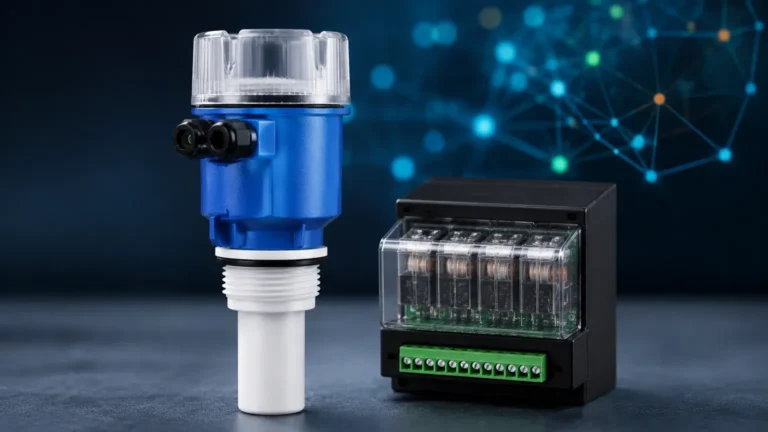
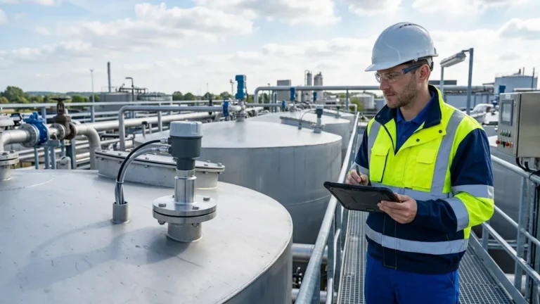
Ultrasonic Level Meter Installation
Ultrasonic Level Meter Installation: A Comprehensive Engineering Guide
In the realm of industrial process control, the accuracy and reliability of level measurement are paramount. Ultrasonic Level Meters have emerged as a preferred non-contact solution for a wide range of applications, from wastewater treatment to chemical storage. However, the performance of these instruments is heavily dependent on correct setup. This guide provides a detailed technical overview of ultrasonic measurement principles and a practical framework for successful ultrasonic level meter installation.
Understanding the Measurement Principle
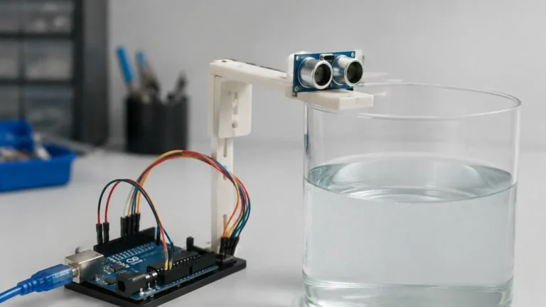
Before proceeding with installation, it is essential to understand how ultrasonic technology functions. Ultrasonic level meters operate on the "Time of Flight" (ToF) principle. The sensor’s transducer emits a high-frequency acoustic pulse—typically between 20 kHz and 200 kHz—that travels through the air toward the material surface.
When the sound wave hits the medium (liquid or solid), it is reflected back to the transducer. The instrument measures the time interval between the emission of the pulse and the reception of the echo. Since the speed of sound in air is known, the distance to the material can be calculated using the formula:
Distance = (Speed of Sound × Time) / 2
The level of the material is then determined by subtracting this distance from the total height of the vessel (the calibration distance).
The Role of Temperature Compensation
The speed of sound is not constant; it varies with the temperature of the medium through which it travels (approximately 0.17% per degree Celsius). Most professional-grade ultrasonic level meters, such as those manufactured by Welk, include an integrated temperature sensor. This allows the internal microprocessor to compensate for temperature fluctuations in real-time, ensuring accuracy remains within the specified tolerance (usually ±0.25% to ±0.5% of the measured range).
Pre-Installation Selection Criteria
Successful ultrasonic level meter installation begins with selecting the correct instrument for the specific application environment. Engineers must evaluate several factors before mounting the device.
1. Measurement Range and Frequency
Lower frequency sensors (e.g., 20–40 kHz) have more energy and can penetrate dust or steam more effectively, making them suitable for longer ranges (up to 30–40 meters). Higher frequency sensors (e.g., 60–80 kHz) offer better resolution and smaller "dead zones" but are limited to shorter ranges (typically under 10 meters).
2. Beam Angle
The ultrasonic pulse does not travel in a straight line; it spreads out in a cone. The beam angle (usually between 5° and 12°) determines the footprint of the signal at the maximum range. If the beam is too wide, it may hit the tank walls or internal structures, causing false echoes.
3. Media Characteristics
While ultrasonic meters are versatile, they are sensitive to the surface condition of the material. Calm liquids provide the best reflection. Turbulent surfaces, foam, or fine powders can scatter or absorb the sound waves, necessitating higher-power sensors or alternative technologies like radar.
Comprehensive Guide to Ultrasonic Level Meter Installation
Proper placement is the most critical factor in ensuring long-term measurement stability. Follow these engineering guidelines for optimal results.
Positioning and Mounting
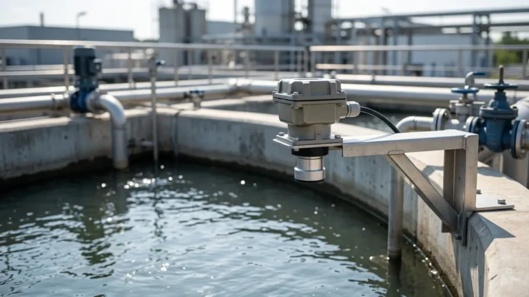
The sensor should be mounted in a location that provides a clear, unobstructed path to the material surface.
* Avoid the Center of the Tank: In tanks with domed or parabolic roofs, do not mount the sensor in the exact center. The curved roof can act as a parabolic reflector, focusing multiple echoes back to the transducer and causing erratic readings.
* Distance from the Wall: The sensor should be installed at a distance from the tank wall at least 1/6th of the tank height. If the sensor is too close to the wall, the beam may interact with the wall surface or buildup on the wall, resulting in false level indications.
* Stay Clear of Inlets: Never install the sensor directly above the fill stream. The falling material will interfere with the ultrasonic pulse and prevent accurate measurement of the surface level.
Managing the Blocking Distance (Dead Zone)
Every ultrasonic sensor has a "blocking distance" or "dead zone" immediately below the transducer face. In this region, the transducer is still vibrating from the emission pulse and cannot accurately receive the returning echo.
If the material level rises into the dead zone, the meter may provide a fixed maximum reading or lose the signal entirely. When planning the ultrasonic level meter installation, ensure the sensor is mounted high enough so that the maximum expected level never enters this zone. For example, if a sensor has a 0.3m (approx. 12") dead zone, the mounting nozzle or bracket should be positioned at least 0.35m above the highest possible liquid level.
Beam Angle and Internal Obstructions
Internal structures such as ladders, heating coils, agitators, and reinforcement beams can create "parasitic echoes."
1. Clear Path: Ensure the entire cone of the ultrasonic beam is clear of obstructions.
2. Agitators: If the tank contains an agitator, the sensor should be positioned where the beam hits the liquid surface at a point where turbulence is minimized. Some modern meters allow for "false echo suppression," where the software is programmed to ignore echoes from fixed internal structures.
3. Perpendicular Alignment: The transducer face must be perfectly parallel to the material surface. Even a few degrees of tilt can cause the echo to reflect away from the sensor, leading to signal loss.
Nozzle and Standpipe Considerations
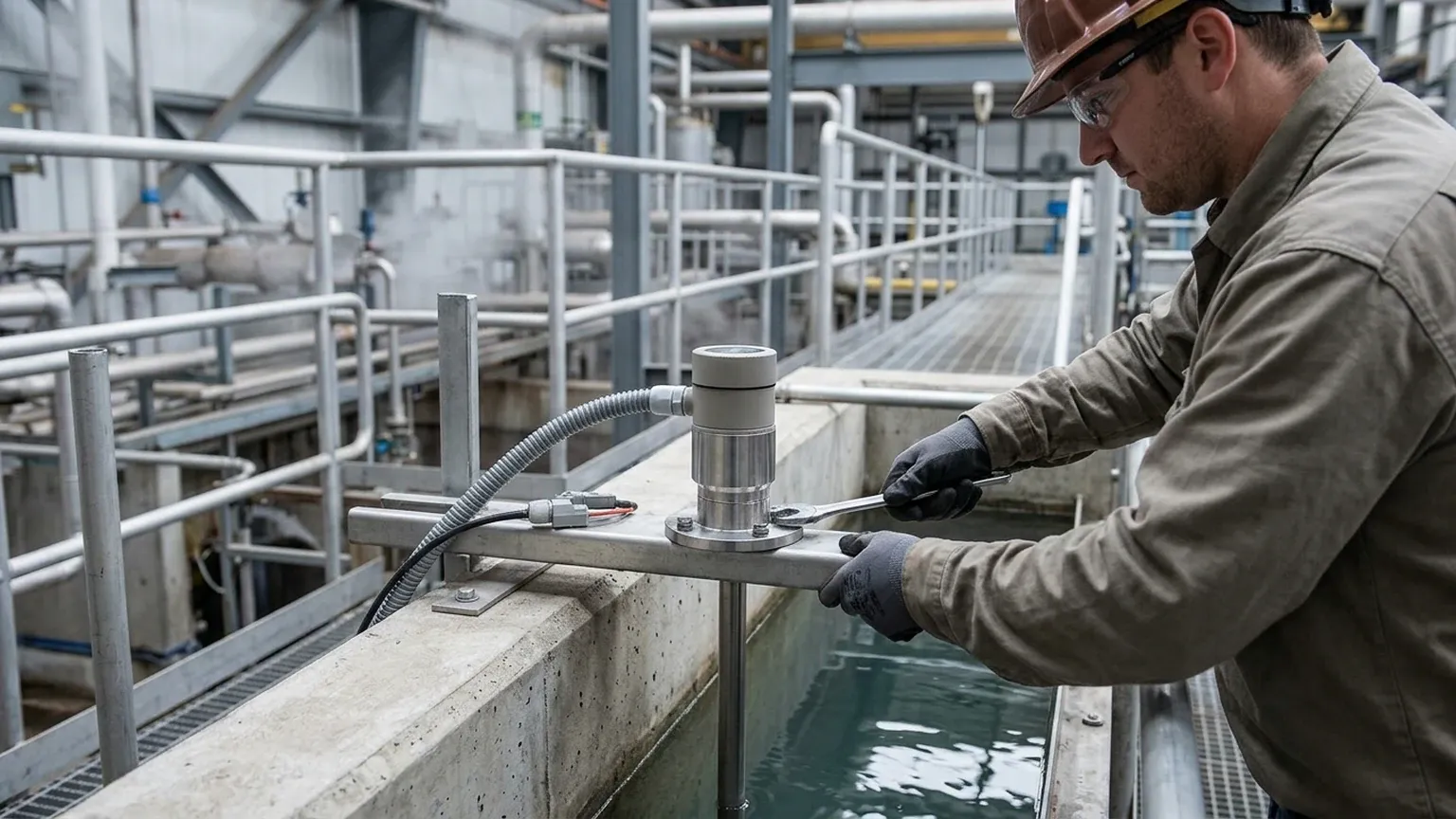
When mounting on a nozzle, the nozzle diameter and height must be considered.
* Nozzle Height: Ideally, the transducer face should protrude slightly below the bottom of the nozzle. If the sensor is recessed inside a long, narrow nozzle, the pulse will bounce off the nozzle walls (ringing), creating interference.
* Standpipes: In applications with heavy foam or extreme turbulence, a standpipe (still-well) can be used. The pipe acts as a waveguide, providing a smooth surface for measurement. The pipe must be vented at the top to equalize pressure and must have a smooth internal surface with no welds or burrs.
Selection and Specification Table
Use the following table as a general reference for matching sensor specifications to common industrial tank configurations.
| Tank Height (m) | Recommended Frequency | Typical Dead Zone (m) | Beam Angle (Typical) | Common Application |
| :— | :— | :— | :— | :— |
| 0 – 5m | 60 – 80 kHz | 0.20m – 0.25m | 8° – 10° | Small chemical tanks, sumps |
| 5 – 12m | 40 – 50 kHz | 0.30m – 0.40m | 10° – 12° | Water storage, buffer tanks |
| 12 – 30m | 20 – 30 kHz | 0.50m – 0.80m | 5° – 8° | Large silos, tall reservoirs |
| Turbulent/Foamy | 20 – 40 kHz | 0.40m – 0.60m | < 10° | Wastewater aeration basins |
Environmental and Media Factors
Vacuum and Pressure
Ultrasonic waves require a medium (air or gas) to travel. Therefore, ultrasonic level meters cannot function in a vacuum. In high-pressure environments, the density of the gas changes, which affects the speed of sound. While some meters can operate up to 3 bar (approx. 43 psi), radar level meters are generally preferred for high-pressure or vacuum vessels.
Heavy Steam and Dust
Dense steam or heavy dust can attenuate the ultrasonic signal. In these environments, selecting a lower-frequency sensor with higher acoustic power is necessary. If the dust is extremely thick (e.g., in a cement silo during filling), the signal may be lost entirely.
Foam and Turbulence
Light, airy foam is a poor reflector of sound; it tends to absorb the ultrasonic pulse. If foam is present, the sensor may report a "lost echo" or measure the top of the foam rather than the liquid. For turbulent liquids, increasing the damping/averaging time in the instrument settings can help stabilize the output signal.
Installation Checklist
Before commissioning the device, verify the following points:
1. Mounting: Is the sensor perpendicular to the liquid surface?
2. Location: Is the sensor away from the tank wall (1/6th height rule)?
3. Obstructions: Is the beam path clear of ladders, pipes, and the fill stream?
4. Dead Zone: Is there sufficient clearance between the sensor and the maximum liquid level?
5. Wiring: Are shielded cables used to prevent EMI/RFI interference? Is the cable gland tightened to maintain the IP rating?
6. Programming: Have the Empty Distance (4mA) and Full Distance (20mA) been correctly entered into the transmitter?
Limitations and Alternative Technologies
While Ultrasonic Level Meters are highly effective, they are not universal solutions. Engineers should consider alternatives in the following scenarios:
* Vacuum Applications: Use Guided Wave Radar (GWR) or Hydrostatic Pressure Transmitters.
* Extreme Temperatures: For process temperatures exceeding 80°C (176°F), standard ultrasonic transducers may fail. High-temperature radar or magnetic level gauges are better suited.
* Thick Foam: If the foam is more than a few centimeters thick, Radar or Hydrostatic sensors are typically more reliable.
* Complex Tank Geometry: In very narrow tanks with many internal obstructions, Guided Wave Radar is often the only viable non-mechanical solution.
Frequently Asked Questions (FAQs)
Q: Can I install an ultrasonic level meter on a plastic tank?
A: Yes. Ultrasonic meters work well on plastic tanks. If the tank is closed, you can mount the sensor on a flange or nozzle. For open-top plastic tanks, a simple bracket mounting is sufficient.
Q: What happens if the sensor gets wet?
A: Most industrial ultrasonic sensors have an IP66, IP67, or IP68 rating. While they can handle moisture and splashing, condensation on the transducer face can temporarily weaken the signal. Many Welk sensors feature a self-cleaning effect where the vibration of the transducer helps shed water droplets.
Q: How do I handle a tank with a sloped bottom?
A: For tanks with conical or sloped bottoms, the "Empty" calibration point should be set to the lowest point where the sensor can still receive a reliable echo. If the sensor is mounted directly over the slope, the signal may reflect away when the tank is nearly empty. In these cases, the meter is usually used for the upper 80-90% of the tank volume.
Q: Is shielded cable necessary for installation?
A: Yes. To prevent electrical noise from VFDs (Variable Frequency Drives) and other industrial equipment from interfering with the 4-20mA or RS485 signal, shielded twisted-pair cable is strongly recommended. The shield should be grounded at the controller end only to avoid ground loops.
By following these technical guidelines and ensuring a precise ultrasonic level meter installation, plant operators can achieve highly accurate, maintenance-free level monitoring across diverse industrial applications. For specific project requirements or custom OEM solutions, consulting with a specialized manufacturer like Welk ensures the technology is perfectly matched to the process conditions.