Ultrasonic Level Sensor Blanking Distance
Ultrasonic Level Sensor Blanking Distance: A Technical Guide for Process Engineers
In the field of industrial automation and process control, achieving accurate inventory and level management depends on selecting the right instrumentation for specific vessel geometries. Among the most versatile tools available are Ultrasonic Level Meters, which provide non-contact measurement for liquids, slurries, and some solids. However, one of the most critical technical constraints that engineers must account for during the design and installation phase is the ultrasonic level sensor blanking distance.
Understanding the "dead zone" or blanking distance is essential for preventing overflow, ensuring continuous data transmission, and maintaining the safety of the storage system. This guide explores the principles of ultrasonic technology, the physical causes of blanking distance, and practical strategies for managing this limitation in industrial environments.
Understanding Ultrasonic Measurement Principles
Before addressing the specifics of blanking distance, it is necessary to understand how ultrasonic technology functions. Ultrasonic level measurement is based on the Time-of-Flight (ToF) principle.
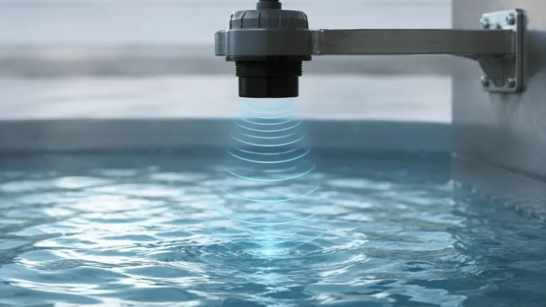
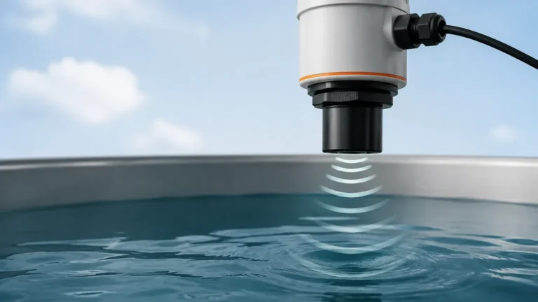
The instrument consists of a transducer containing a piezoelectric crystal. When energized, this crystal vibrates at a high frequency, emitting a series of ultrasonic pulses (sound waves) toward the target medium. These waves travel through the air space above the material, strike the surface, and are reflected back to the sensor. The sensor then switches from "transmit" to "receive" mode to detect the returning echo.
The distance ($D$) from the sensor to the material surface is calculated using the formula:
$$D = \frac{c \times t}{2}$$
Where:
- $c$ is the speed of sound in the medium (typically air, approximately 344 m/s at 20°C).
- $t$ is the total time elapsed between the emission of the pulse and the reception of the echo.
By subtracting this distance from the known total height of the tank, the electronics determine the level of the material. Because this method is non-contact, Ultrasonic Level Meters are ideal for corrosive, coating, or high-viscosity fluids where traditional contact probes might fail.
Defining Ultrasonic Level Sensor Blanking Distance
The ultrasonic level sensor blanking distance (also referred to as the "dead zone" or "near-field") is the area directly beneath the sensor face where the instrument cannot accurately process a return signal.
If the material surface enters this zone, the sensor may produce erratic readings, report a "lost echo" error, or jump to a maximum level reading. In a practical sense, if a sensor has a blanking distance of 0.3 meters (300 mm), any material within 300 mm of the sensor face is effectively invisible to the device. This physical limitation is a characteristic of all pulse-echo ultrasonic transducers and must be factored into the effective measuring range of the vessel.
Why Blanking Distance Occurs: The Physics of Transducers
The existence of a blanking distance is not a manufacturing flaw but a result of the physical properties of the piezoelectric transducer. This phenomenon is caused by a process known as "ringing."
When the piezoelectric crystal is excited by an electrical pulse, it begins to vibrate mechanically to create the sound wave. Once the electrical pulse stops, the crystal does not stop vibrating instantaneously. Like a bell that has been struck, the transducer continues to vibrate for a short duration. This residual vibration is called ringing.
During this ringing period, the sensor’s electronics are unable to distinguish between the residual vibration of the transducer itself and the weak echo returning from a nearby surface. To prevent false readings caused by its own vibration, the sensor is programmed with a "blanking period"—a brief window of time during which the receiver is ignored. The distance the sound wave travels during this blanking period defines the physical blanking distance.
Relationship Between Frequency and Blanking
There is a direct relationship between the operating frequency of the sensor and the size of the dead zone:
- High-Frequency Sensors (e.g., 60 kHz – 80 kHz): These sensors use smaller crystals that stop vibrating more quickly. Consequently, they have shorter blanking distances (often 0.2m to 0.25m) but a shorter overall effective range.
- Low-Frequency Sensors (e.g., 20 kHz – 30 kHz): These sensors use larger, more powerful crystals to measure over long distances (up to 30 or 40 meters). Because the larger mass of the crystal rings for a longer duration, these sensors have much larger blanking distances (often 0.6m to 1.0m).
Engineering Implications of the Dead Zone
Failing to account for the ultrasonic level sensor blanking distance can lead to significant operational risks.
1. Tank Overfills: If the high-level alarm is set within the blanking zone, the sensor may fail to trigger the alarm as the liquid rises, leading to an environmental spill or equipment damage.
2. Erratic Control Loops: In automated filling systems, if the level reaches the dead zone, the sensor might output a zero-level signal or a maximum-level signal intermittently. This causes pumps to cycle rapidly (chattering) or fail to shut off.
3. Reduced Effective Capacity: The usable volume of a tank is effectively reduced by the depth of the blanking zone unless the sensor is mounted in a way that places the dead zone above the maximum fill line.
Selection Criteria and Technical Specifications
When selecting a sensor from a manufacturer like Welk, it is vital to match the sensor’s range and blanking distance to the specific dimensions of your tank. Below is a general reference table illustrating the relationship between maximum range and blanking distance for typical industrial ultrasonic level meters.
Typical Selection Table
| Maximum Measuring Range (m) | Typical Blanking Distance (m) | Ideal Application |
| :— | :— | :— |
| 4.0m | 0.20m – 0.25m | Small chemical tanks, sumps |
| 8.0m | 0.30m – 0.35m | Standard process vessels, water storage |
| 12.0m | 0.45m – 0.50m | Large silos, wastewater basins |
| 20.0m+ | 0.60m – 1.20m | Deep wells, large grain silos |
*Note: These values are indicative. Always refer to the specific datasheet of the model provided by the manufacturer.*

Installation Strategies to Manage Blanking Distance
To maximize the usable volume of a tank while using ultrasonic technology, engineers employ several installation techniques to "move" the blanking distance out of the way of the process material.
1. Nozzle Mounting
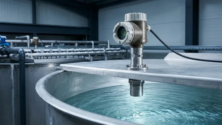
If the tank must be filled to the very top, the sensor can be mounted on a nozzle or a standpipe. By raising the sensor face above the top of the tank, the blanking distance is contained within the nozzle itself.
Considerations for Nozzle Mounting:
- Diameter: The nozzle must be wide enough so that the ultrasonic beam (which spreads in a cone shape, typically 5° to 12°) does not strike the sides of the nozzle. Internal reflections from the nozzle wall can cause false echoes.
- Smoothness: The interior of the nozzle should be smooth and free of burrs or weld seams.
- Length: The nozzle should be long enough to clear the blanking distance but not so long that it interferes with the beam spread.
2. Bracket Mounting
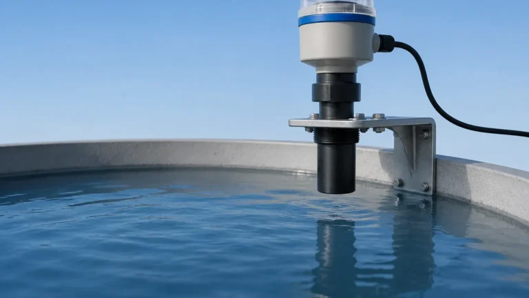
In open-air applications, such as river level monitoring or open sumps, the sensor is often mounted on an L-bracket extending over the water. By simply mounting the bracket higher than the maximum expected flood level (plus the blanking distance), the dead zone issue is eliminated.
3. Avoiding Obstructions
Because the ultrasonic beam expands as it travels, the sensor should be placed away from ladders, fill pipes, and agitators. If an obstruction is located within the blanking zone or just below it, the sensor may lock onto that fixed object instead of the liquid surface.
Common Risks and Troubleshooting
Even with proper installation, certain process conditions can affect how the sensor handles the blanking distance:
* Foam: Heavy foam can absorb the ultrasonic signal. If foam enters the blanking zone, the sensor is highly likely to lose the signal entirely.
* Temperature Gradients: Rapid temperature changes can shift the speed of sound. While most Welk sensors include integrated temperature compensation, extreme fluctuations near the transducer face can affect the accuracy of the blanking boundary.
* Vapor and Condensation: While ultrasonic sensors are robust, heavy condensation on the transducer face can extend the ringing time, effectively increasing the blanking distance temporarily until the droplets fall off.
What happens if the level enters the dead zone?
Most modern digital ultrasonic level meters allow the user to define the "Error Action." If the surface enters the blanking zone, the sensor can be programmed to:
- Hold the last valid measurement.
- Output a specific error current (e.g., 22mA or 3.8mA).
- Report the maximum tank height (assuming the tank is full).
Frequently Asked Questions
Q: Can I reduce the blanking distance through software settings?
A: No. The blanking distance is a physical limitation based on the transducer's mechanical ringing. While you can increase the blanking distance in the software (to ignore internal tank obstructions near the top), you cannot decrease it below the factory-defined physical minimum.
Q: Is blanking distance the same as the sensor's accuracy?
A: No. Accuracy refers to the precision of the measurement within the valid range (typically ±0.2% to ±0.5% of the span). Blanking distance is the minimum range requirement where measurement is possible.
Q: Do radar level meters have the same blanking distance as ultrasonic meters?
A: Radar (microwave) level meters also have a "near-field" or dead zone, but it is typically much smaller than that of ultrasonic sensors (often as little as 50mm) because electromagnetic waves do not cause the same mechanical ringing effect as sound waves.
Q: How do I choose between a 5m and a 10m sensor if my tank is 4.5m deep?
A: While a 5m sensor covers the depth, it will have a smaller blanking distance, allowing you to fill the tank higher. However, if there is heavy dust or steam, the 10m sensor (which has a more powerful pulse) might be more reliable despite its larger blanking distance. Always prioritize the signal reliability for the specific medium.
Conclusion
Successful implementation of Ultrasonic Level Meters requires a balance between the required measuring range and the physical constraints of the ultrasonic level sensor blanking distance. By understanding that the dead zone is a byproduct of transducer ringing, engineers can design mounting solutions—such as standpipes or elevated brackets—that ensure the sensor remains accurate even when the vessel is at maximum capacity.
When selecting instrumentation, always verify the blanking specifications against your high-level alarm setpoints. For complex applications involving narrow nozzles or turbulent surfaces, consulting with a technical specialist can ensure that the selected device provides the reliability and safety required for industrial process control.