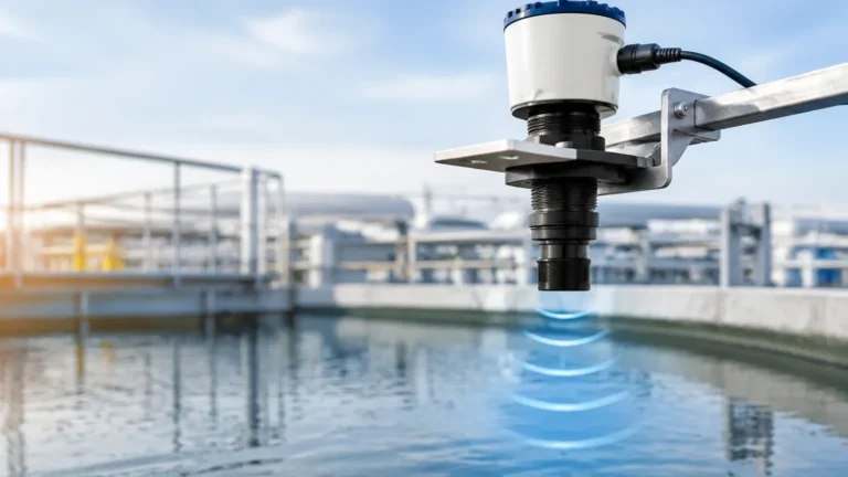
Ultrasonic Level Sensor 4 20ma
Ultrasonic Level Sensor 4-20mA: A Comprehensive Engineering Guide to Selection and Application
In the landscape of industrial automation, the ability to monitor liquid and solid levels accurately without physical contact is a critical requirement for operational efficiency and safety. The ultrasonic level sensor 4 20ma has emerged as a cornerstone technology for these applications. By combining non-contact ultrasonic measurement with the industry-standard 4-20mA analog output, these instruments provide a reliable bridge between physical process conditions and control systems like PLCs (Programmable Logic Controllers) and SCADA networks.
As a professional manufacturer of industrial level measurement instruments, Welk provides high-performance Ultrasonic Level Meters designed for diverse environments, ranging from municipal water treatment to complex chemical processing. This guide explores the fundamental principles, selection criteria, and installation best practices for 4-20mA ultrasonic sensors.
Understanding the Measurement Principle
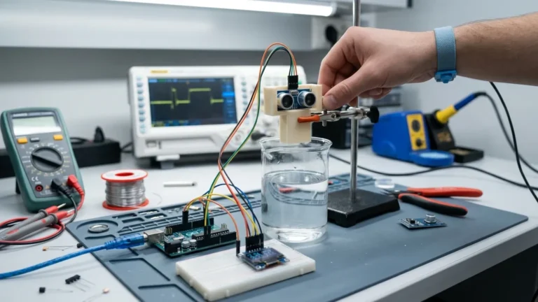
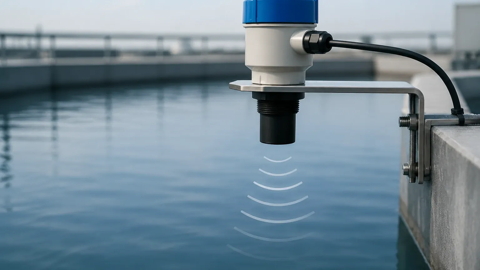
Ultrasonic level measurement is based on the "Time-of-Flight" (ToF) principle. The sensor’s transducer emits a high-frequency ultrasonic pulse (typically between 20 kHz and 200 kHz). This sound wave travels through the air, strikes the surface of the medium (liquid or solid), and reflects back to the transducer.
The Calculation Process
The sensor’s internal microprocessor measures the time interval between the emission of the pulse and the reception of the echo. The distance to the surface is calculated using the formula:
Distance = (Speed of Sound × Time) / 2
Since the speed of sound in air is approximately 344 m/s (1,128 ft/s) at 20°C (68°F), the device can determine the distance with high precision. By subtracting this distance from the total tank height (the "empty" calibration point), the instrument determines the actual level of the material.
The Role of the 4-20mA Signal
The ultrasonic level sensor 4 20ma converts this calculated level into a proportional current signal. In a standard configuration:
* 4mA represents the 0% level (empty tank).
* 20mA represents the 100% level (full tank).
The 4-20mA current loop is favored in industrial environments because it is highly resistant to electrical noise and can transmit signals over long distances (up to 1,000 meters or 3,280 feet) without significant signal degradation. Furthermore, the "live zero" (4mA) allows the control system to distinguish between a zero-level reading and a broken wire (0mA).
Key Evaluation and Selection Criteria
Choosing the right ultrasonic level sensor requires a detailed understanding of the application environment. Engineers must evaluate several technical parameters to ensure long-term reliability.
1. Measuring Range and Dead Zone
Every ultrasonic sensor has a "dead zone" (or blocking distance) directly beneath the transducer where measurement is impossible. This occurs because the transducer cannot receive an echo while it is still vibrating from the pulse emission. Typical dead zones range from 0.2m to 0.5m (0.66 ft to 1.64 ft). When selecting a sensor, ensure the maximum expected liquid level does not enter this zone.
2. Beam Angle
The ultrasonic pulse spreads out in a cone shape. If the beam angle is too wide, the signal may reflect off tank walls, ladders, or agitators, causing false readings. Narrower beam angles (typically 5° to 12°) are preferred for tall, narrow tanks or vessels with internal obstructions.
3. Material Compatibility
For corrosive environments, such as acid or alkali storage, the transducer face must be constructed from chemically resistant materials like PVDF (Polyvinylidene Fluoride) or PTFE (Polytetrafluoroethylene). Standard applications often use ABS or PVC housings.
4. Integrated vs. Split Design
* Integrated (Compact) Type: The transducer and electronics are housed in a single unit. This is cost-effective and easier to install for standard applications.
* Split (Remote) Type: The transducer is mounted at the measurement point, while the display and 4-20mA output electronics are mounted in a remote, accessible location (e.g., a control room or eye-level wall). This is ideal for hazardous areas or where the measurement point is difficult to access.
Selection Table: Ultrasonic Level Sensor Configurations
| Feature | Standard Integrated | High-Precision Split Type | Chemical Resistant Model |
| :— | :— | :— | :— |
| Measuring Range | 0.4m – 10m | 0.5m – 30m | 0.3m – 12m |
| Output Signal | 4-20mA / RS485 | 4-20mA / Relays / RS485 | 4-20mA / HART |
| Accuracy | ±0.5% FS | ±0.25% FS | ±0.5% FS |
| Beam Angle | 10° – 12° | 5° – 8° | 9° – 11° |
| Housing Material | ABS / Plastic | Cast Aluminum / ABS | PVDF / PTFE |
| Power Supply | 24V DC (2-wire/4-wire) | 220V AC or 24V DC | 24V DC |
Installation Considerations for Maximum Accuracy
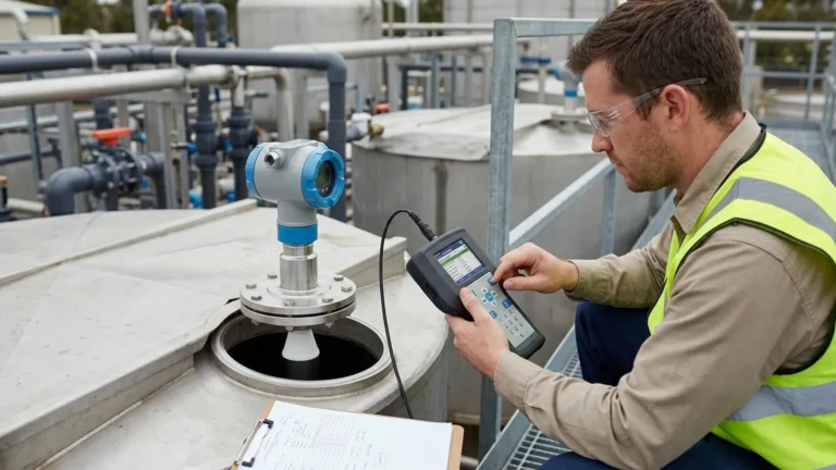
Proper installation is the most significant factor in the performance of an ultrasonic level sensor 4 20ma. Follow these engineering guidelines to avoid common pitfalls:
1. Perpendicular Alignment: The transducer face must be perfectly parallel to the liquid surface. Even a few degrees of tilt can cause the echo to reflect away from the sensor, resulting in signal loss.
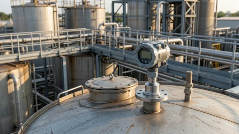
2. Avoid the Center of Domed Tanks: In tanks with domed or parabolic tops, do not mount the sensor in the exact center. The shape of the roof can act as a parabolic reflector, concentrating multiple echoes and causing erratic readings.
3. Stay Away from Inlets: Never install the sensor directly above the fill stream. The falling liquid or resulting turbulence/foam will interfere with the ultrasonic pulse.
4. Clear Path: Ensure there are no structural supports, pipes, or ladders within the ultrasonic beam cone. If obstructions are unavoidable, many modern Ultrasonic Level Meters offer "false echo suppression" software to ignore these fixed reflections.
5. Sunlight and Temperature Protection: While most sensors include internal temperature compensation (to account for changes in the speed of sound), direct sunlight can heat the sensor housing unevenly. Using a sunshade is recommended for outdoor installations to maintain accuracy.
Limitations and Environmental Factors
While ultrasonic sensors are versatile, they are not suitable for every application. Engineers should be aware of the following limitations:
* Vacuum Conditions: Sound waves require a medium (air or gas) to travel. Ultrasonic sensors will not work in a vacuum.
* Heavy Foam: Thick, dense foam on the liquid surface acts as an acoustic absorber, soaking up the ultrasonic pulse rather than reflecting it. In these cases, hydrostatic or radar level transmitters may be more appropriate.
* Extreme Dust or Vapor: While light dust is manageable, extremely dense dust (in silos) or heavy steam/vapor can attenuate the signal. High-power transducers or radar technology are often substituted in these scenarios.
* High Pressure/Temperature: Standard ultrasonic sensors are typically rated for atmospheric pressure and temperatures below 80°C (176°F). Beyond these limits, the change in air density significantly affects the speed of sound and signal integrity.
Common Risks and Mitigation
The primary risk in deploying an ultrasonic level sensor 4 20ma is "lost echo" syndrome. This occurs when the sensor cannot detect a return signal, often due to excessive turbulence, foam, or improper mounting.
Mitigation Strategies:
* Damping/Averaging: Configure the sensor’s software to average multiple readings, which helps stabilize the 4-20mA output in turbulent tanks.
* Stilling Wells: For highly turbulent liquids, installing the sensor inside a vertical pipe (stilling well) can provide a calm surface for measurement.
* Proper Sizing: Always select a sensor with a range at least 20-25% greater than the actual tank height to ensure a strong signal even in sub-optimal conditions.
Frequently Asked Questions (FAQs)
Q: Can a 4-20mA ultrasonic sensor be used for solids like grain or sand?
A: Yes, but with caveats. Solids do not reflect sound as efficiently as liquids and often form a conical pile rather than a flat surface. You must select a sensor specifically rated for solids, usually with a higher power output and a narrower beam.
Q: What is the difference between a 2-wire and a 4-wire 4-20mA sensor?
A: A 2-wire sensor uses the same two wires for both power and signal (loop-powered). A 4-wire sensor uses two wires for power (often 220V AC or 24V DC) and two separate wires for the 4-20mA signal. 4-wire sensors generally offer higher pulse power for more challenging applications.
Q: How does temperature affect the 4-20mA output?
A: The speed of sound changes by approximately 0.17% per degree Celsius. Most Welk ultrasonic sensors include a built-in temperature probe to automatically compensate for this, ensuring the 4-20mA signal remains accurate across varying ambient temperatures.
Conclusion
The ultrasonic level sensor 4 20ma remains a preferred choice for industrial level monitoring due to its non-contact nature, ease of integration, and cost-effectiveness. By understanding the acoustic principles and environmental constraints discussed in this guide, project managers and engineers can select the most appropriate instrumentation for their specific needs.
For technical specifications and to explore our range of reliable measurement solutions, visit our dedicated section on Ultrasonic Level Meters. Whether your application involves water treatment, chemical storage, or industrial automation, Welk provides the expertise and hardware to ensure precise, maintenance-free level control.