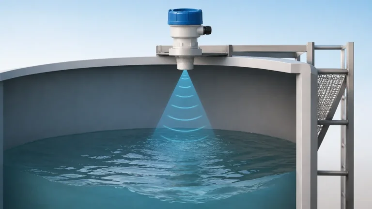
Ultrasonic Level Sensor Working Principle
Ultrasonic Level Sensor Working Principle: A Comprehensive Engineering Guide
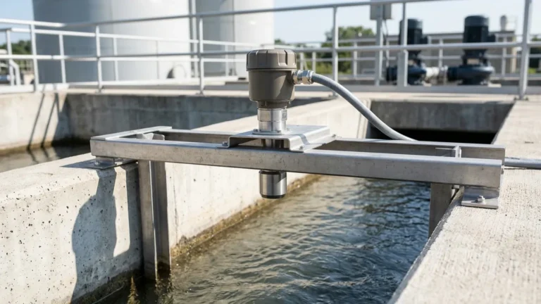
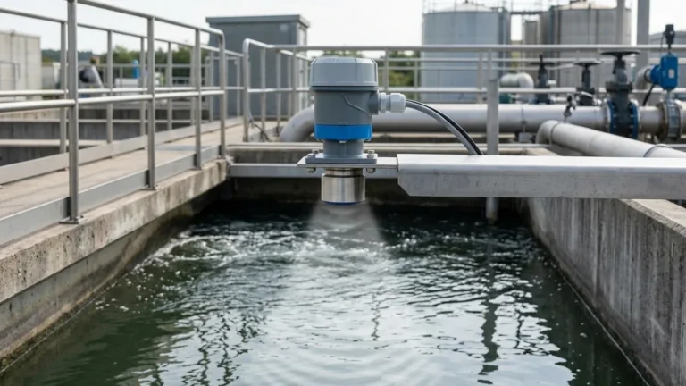
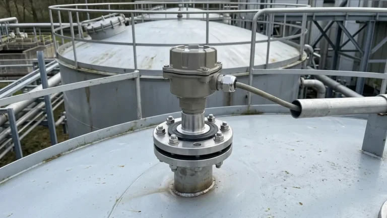
In industrial process automation, the ability to monitor liquid and solid levels without physical contact is a significant advantage. Among the various technologies available, ultrasonic level measurement remains one of the most versatile and cost-effective solutions for water treatment, chemical processing, and general manufacturing. Understanding the ultrasonic level sensor working principle is essential for engineers and technicians to ensure accurate installation, reliable data, and long-term system stability.
As a professional manufacturer, Welk provides high-performance Ultrasonic Level Meters designed to meet the rigorous demands of modern industrial environments. This guide explores the physics behind the technology, selection criteria, and practical application considerations.
The Fundamental Physics of Ultrasonic Measurement
Ultrasonic waves are sound waves with frequencies higher than the upper audible limit of human hearing, typically starting at 20 kHz. In industrial level measurement, sensors usually operate in the range of 40 kHz to 200 kHz. The higher the frequency, the shorter the range but the higher the resolution; conversely, lower frequencies can travel further but are more susceptible to environmental noise.
The Time-of-Flight (ToF) Principle
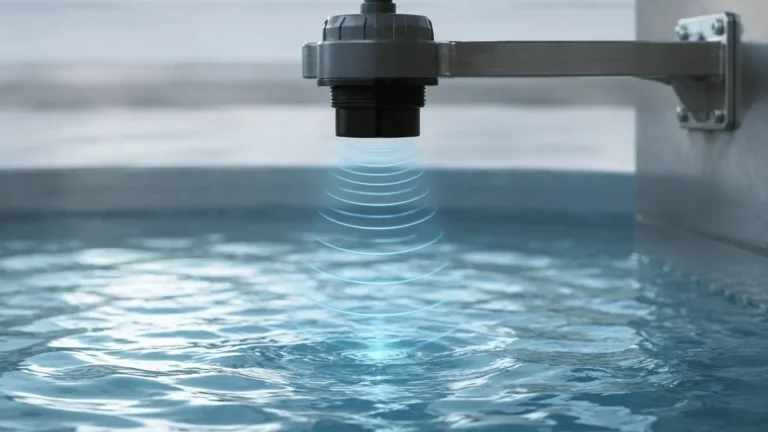
The core of the ultrasonic level sensor working principle is the Time-of-Flight (ToF) measurement. The process follows a specific sequence:
1. Emission: The sensor's transducer (typically containing a piezoelectric crystal) is excited by an electrical pulse, causing it to vibrate and emit a burst of ultrasonic sound waves toward the target material.
2. Propagation: The sound waves travel through the air or gas medium in the tank at the speed of sound.
3. Reflection: Upon hitting the surface of the medium (liquid or solid), a portion of the sound energy is reflected back toward the sensor. This reflected signal is known as an "echo."
4. Detection: The transducer receives the echo and converts the mechanical vibration back into an electrical signal.
5. Calculation: The internal electronics measure the time interval between the emission of the pulse and the reception of the echo.
The distance ($D$) between the sensor and the material surface is calculated using the following formula:
$$D = \frac{c \times t}{2}$$
Where:
* $c$ is the speed of sound in the medium (approximately 343 m/s in air at 20°C).
* $t$ is the total time elapsed (round trip).
Since the height of the vessel ($H$) is a known constant, the actual level ($L$) of the material is determined by subtracting the measured distance from the total height: $L = H – D$.
Key Components of Ultrasonic Level Meters
To understand how these devices function in the field, it is helpful to break down the primary components found in modern Ultrasonic Level Meters.
1. The Transducer
The transducer is the heart of the instrument. It utilizes the piezoelectric effect to act as both a transmitter and a receiver. When an alternating current is applied to the piezoelectric crystal, it expands and contracts rapidly, creating sound waves. When the echo returns, the mechanical pressure on the crystal generates a small voltage that the electronics can process.
2. Signal Processing Electronics
Modern sensors utilize advanced Digital Signal Processing (DSP). This allows the meter to filter out "false echoes" caused by internal tank obstructions like ladders, agitators, or weld seams. Intelligent algorithms can distinguish the true level from background noise, ensuring stability in turbulent conditions.
3. Temperature Compensation
The speed of sound is not constant; it changes significantly with temperature. In air, the speed of sound increases by approximately 0.6 m/s for every degree Celsius increase. Therefore, professional-grade sensors include an integrated temperature sensor to provide real-time compensation, maintaining accuracy across fluctuating process temperatures.
Selection Criteria for Industrial Applications
Choosing the right instrument requires matching the sensor specifications to the specific environment. The following table provides a quick reference for selection based on common industrial parameters.
| Parameter | Requirement | Consideration |
| :— | :— | :— |
| Measurement Range | 0.2m to 30m | Higher ranges require lower frequency transducers. |
| Medium State | Liquid vs. Solid | Liquids provide a flat reflective surface; solids require higher power due to signal scattering. |
| Process Temperature | -40°C to +80°C | Ensure the sensor has integrated temperature compensation. |
| Process Pressure | Atmospheric to 0.3 MPa | Ultrasonic waves do not travel in a vacuum and struggle in high-pressure gas. |
| Chemical Compatibility | Corrosive vs. Inert | Use PVDF or PTFE-faced transducers for acids and alkalis. |
| Output Signal | 4-20mA, RS485, HART | Match the signal to the local PLC or SCADA system. |
Practical Installation Considerations
Even the most advanced ultrasonic level sensor working principle cannot overcome poor installation. To achieve reliable results, engineering teams must follow strict mounting guidelines.
The Dead Zone (Blocking Distance)
Every ultrasonic sensor has a "Dead Zone" directly beneath the transducer face. This is the distance required for the transducer to stop vibrating after the pulse is sent so it can begin listening for the return echo. If the material level enters this zone, the sensor cannot provide a reading.
* Guideline: Mount the sensor high enough so the maximum expected level never enters the dead zone (typically 0.2m to 0.5m depending on the model).
Beam Angle and Obstructions
The ultrasonic pulse is emitted in a cone shape, known as the beam angle (usually between 5° and 12°). Any object within this cone—such as a pipe, a cooling coil, or a ladder—will create a false echo.
* Guideline: Ensure the path of the beam is clear of obstructions. If an obstruction is unavoidable, use a sensor with "false echo suppression" software to ignore the static reflection.
Mounting Orientation
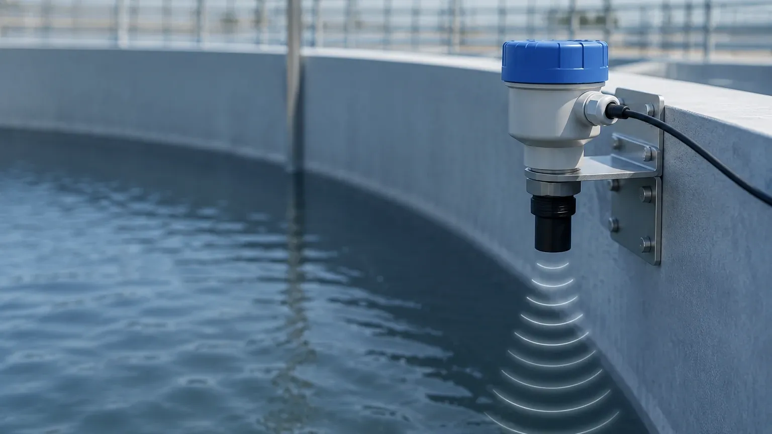
The transducer face must be perfectly parallel to the liquid surface. If the sensor is tilted, the sound waves will reflect away from the transducer rather than back toward it, resulting in a "Loss of Echo" (LOE) error.
* Guideline: Use a spirit level during installation. For solids with an angle of repose, a swiveling flange may be necessary to aim the sensor at the most representative point of the pile.
Environmental Limitations and Challenges
While ultrasonic technology is robust, certain process conditions can interfere with the sound wave propagation:
1. Heavy Foam: Dense foam on a liquid surface absorbs the ultrasonic signal rather than reflecting it. In these cases, a radar level meter or a magnetic level gauge may be a better choice.
2. Vacuum Conditions: Sound requires a medium (gas/air) to travel. Ultrasonic sensors will not work in a vacuum.
3. Heavy Dust or Steam: While light dust is manageable, extremely heavy dust or thick steam can attenuate the signal. High-power transducers can often overcome this, but it must be accounted for during the design phase.
4. Turbulence: Rapidly agitating liquids can cause the surface to be uneven, scattering the echo. Signal averaging and damping settings in the electronics can help stabilize the reading.
Maintenance and Troubleshooting
One of the primary benefits of the non-contact ultrasonic level sensor working principle is the minimal maintenance required. Since no parts touch the process media, there is no mechanical wear or buildup on moving parts.
* Transducer Cleaning: In high-humidity or dusty environments, condensation or dust may accumulate on the transducer face. A periodic wipe with a soft cloth is usually sufficient.
* Signal Loss: If the sensor displays a "Loss of Echo" message, check for foam, excessive turbulence, or if the material has entered the dead zone.
* Accuracy Drift: If the level reading is consistently off by a small percentage, verify the temperature compensation settings or check if the speed of sound has changed due to a different gas composition in the tank (e.g., high concentrations of CO2).
Frequently Asked Questions (FAQ)
Q: Can ultrasonic sensors measure the level of solids like sand or grain?
A: Yes, but with caveats. Solids scatter the sound waves and often have an uneven surface. It is recommended to use a sensor with a higher power output and a narrower beam angle for these applications.
Q: How does wind affect an outdoor ultrasonic sensor?
A: Strong winds can "blow" the sound wave away, potentially causing signal loss. For outdoor installations in open channels, using a protective shroud or a stilling well can mitigate this effect.
Q: What is the difference between a 2-wire and a 4-wire ultrasonic level meter?
A: A 2-wire sensor uses the same two wires for both power and the 4-20mA output signal, making it easier to wire but offering less power for the transducer. A 4-wire sensor has separate wires for power (usually 24VDC or 220VAC) and signal, allowing for higher-power pulses and longer measurement ranges.
Q: Can I use an ultrasonic sensor in a pressurized tank?
A: Ultrasonic sensors can typically handle moderate pressures (up to 0.3 MPa). However, as pressure increases, the speed of sound changes, and the transducer's ability to vibrate is dampened. For high-pressure vessels, radar technology is generally preferred.
Conclusion
Understanding the ultrasonic level sensor working principle allows engineers to deploy these tools effectively across a wide range of industrial scenarios. By accounting for variables like temperature, beam angle, and the dead zone, users can ensure high-precision measurement with minimal maintenance overhead.
For those seeking reliable, industrial-grade solutions, Welk offers a diverse range of Ultrasonic Level Meters tailored for everything from simple water tank monitoring to complex chemical process control. By selecting the right technology and following proper installation protocols, facilities can achieve the accuracy and safety required for modern automated operations.