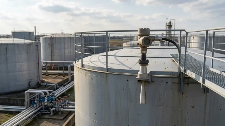
Ultrasonic Level Transmitters
Ultrasonic Level Transmitters: A Comprehensive Engineering Guide
In the landscape of industrial automation, precise inventory management and process control rely heavily on accurate level measurement. Among the various technologies available, ultrasonic level transmitters have emerged as a preferred non-contact solution for a wide range of liquid and solid applications. This guide provides a technical overview of how these instruments operate, their selection criteria, and the practical considerations necessary for successful implementation in industrial environments.
Measurement Principles of Ultrasonic Technology
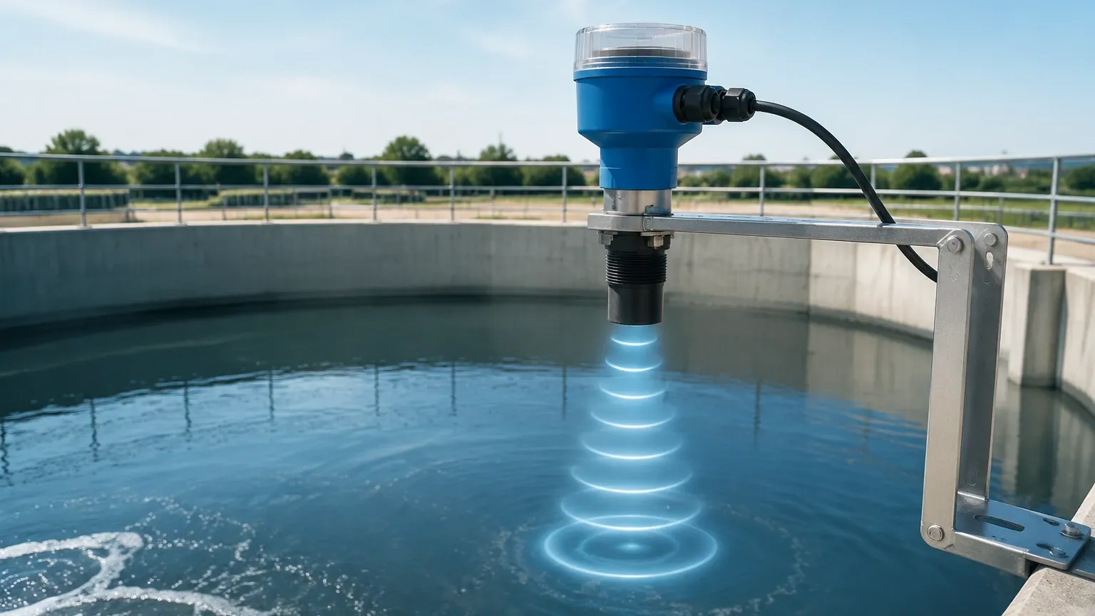
Ultrasonic level measurement is based on the "Time-of-Flight" (ToF) principle. The device, often referred to as one of the primary Ultrasonic Level Meters, utilizes a piezoelectric transducer to emit high-frequency sound pulses, typically in the range of 20 kHz to 70 kHz.
The Pulse-Echo Sequence
1. Emission: The transducer converts electrical energy into an ultrasonic pulse that travels through the air or gas space toward the material surface.
2. Reflection: When the sound wave hits the surface of the medium (liquid or solid), a portion of the energy is reflected back toward the sensor as an echo.
3. Detection: The transducer receives the returning echo and converts the mechanical energy back into an electrical signal.
4. Calculation: The internal electronics measure the time interval ($t$) between the emission of the pulse and the reception of the echo.
The distance ($D$) from the sensor to the material surface is calculated using the formula:
$$D = \frac{c \times t}{2}$$
Where $c$ is the speed of sound in the medium (usually air). Since the total distance traveled is to the surface and back, the result is divided by two. The transmitter then subtracts this distance from the total tank height (programmed during commissioning) to determine the actual level of the product.
Temperature Compensation
The speed of sound is not constant; it fluctuates based on the temperature of the medium through which it travels. In air, the speed of sound changes by approximately 0.17% per degree Celsius. To maintain accuracy, modern ultrasonic level transmitters include a built-in temperature sensor to provide real-time compensation for these variations. For applications with significant temperature gradients, external temperature sensors may be integrated to ensure the calculation remains precise.
Key Evaluation Criteria for Selection
Selecting the correct instrument requires an understanding of the process environment and the physical properties of the substance being measured. Engineers should evaluate the following factors before specifying a device.
Measuring Range and Frequency
The frequency of the ultrasonic pulse determines the effective measuring range. Lower frequencies (e.g., 20-30 kHz) have longer wavelengths and can travel further, making them suitable for ranges up to 30 meters (approx. 98 ft) or for penetrating dust. Higher frequencies (e.g., 50-70 kHz) offer better resolution and smaller "dead zones" but are limited to shorter distances, typically under 10 meters (approx. 33 ft).
Process Conditions: Pressure and Temperature
Ultrasonic waves require a medium (gas) to propagate. Therefore, these sensors cannot function in a vacuum. Most standard ultrasonic level transmitters are designed for atmospheric pressure or very low-pressure vessels (typically up to 3 bar / 43.5 psi). Similarly, while temperature compensation handles ambient fluctuations, the maximum operating temperature for the transducer face is generally limited to 80°C or 100°C (176°F to 212°F) due to the limitations of the piezoelectric materials and housing.
Chemical Compatibility
The transducer is the only part of the instrument exposed to the process vapors. Welk offers transducers constructed from various materials, including Polypropylene (PP), Polyvinylidene Fluoride (PVDF), or PTFE. PVDF is often selected for corrosive chemical storage, such as sulfuric acid or sodium hypochlorite, due to its superior chemical resistance.
Practical Selection Table
The following table provides a general comparison of common ultrasonic configurations used in industrial automation.
| Feature | Compact (Two-Wire) | Remote / Split System | High-Power Version |
| :— | :— | :— | :— |
| Typical Range | 0.25m – 12m | 0.4m – 30m | Up to 40m |
| Power Supply | 24V DC (Loop Powered) | 220V AC or 24V DC | 220V AC |
| Output | 4-20mA HART | 4-20mA, Relays, RS485 | 4-20mA, RS485, Relays |
| Best For | Standard liquid tanks | Tall silos, sumps | Solids, powders, dust |
| Installation | Simple, integrated | Display at eye level | Heavy industrial use |
Installation Considerations
Correct physical installation is the most critical factor in ensuring the reliability of Ultrasonic Level Meters. Even the most advanced signal processing cannot compensate for a poorly placed sensor.
The Dead Band (Blocking Distance)
Every ultrasonic sensor has a "dead band" or blocking distance immediately below the transducer face where measurement is impossible. This occurs because the transducer cannot switch from "transmit" to "receive" mode instantaneously. If the liquid level enters this zone, the device will report an error or provide a false reading. Always mount the transmitter high enough so that the maximum expected level remains below the dead band (typically 0.2m to 0.5m depending on the model).
Beam Angle and Obstructions
The ultrasonic pulse spreads out in a cone shape, usually between 5° and 12°. It is essential to ensure that no internal tank obstructions—such as ladders, heating coils, or agitators—intersect this beam. If an obstruction is unavoidable, many Welk transmitters feature "False Echo Suppression" software, allowing the engineer to map out and ignore static reflections from fixed objects.
Mounting Orientation
* Perpendicularity: The transducer face must be mounted perfectly parallel to the liquid surface. A tilt of even a few degrees can cause the reflected signal to miss the receiver, leading to signal loss.
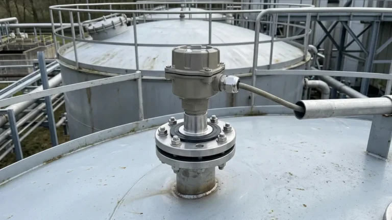
* Nozzle Length: If mounting on a standpipe or nozzle, the nozzle must be short enough so that the ultrasonic beam clears the bottom edge of the pipe to prevent internal interference.
* Inlet Proximity: Do not mount the sensor directly over the tank inlet. Falling liquid or turbulent inflow will disrupt the surface and create noise that interferes with the echo.
Limitations and Common Risks
While versatile, ultrasonic technology is not a universal solution. Engineers must be aware of specific conditions that can degrade performance:
1. Heavy Foam: Surface foam acts as an acoustic absorber. Light, airy foam may simply decrease the signal strength, but dense, thick foam can completely absorb the ultrasonic pulse, resulting in a "Lost Echo" error. In such cases, radar or hydrostatic transmitters may be more appropriate.
2. Vapor and Steam: While the sensor can compensate for temperature, heavy steam or high concentrations of chemical vapors can change the density of the gas space, altering the speed of sound and introducing measurement errors.
3. Vacuum Conditions: As sound requires a medium to travel, ultrasonic sensors will not work in a vacuum.
4. Dusty Environments: In solid level measurement (e.g., grain or cement), heavy dust can scatter the signal. High-power, low-frequency transmitters are required for these applications to ensure the pulse can penetrate the air-borne particles.
Applications in Industry
Ultrasonic level transmitters are widely deployed across multiple sectors due to their cost-effectiveness and ease of maintenance.
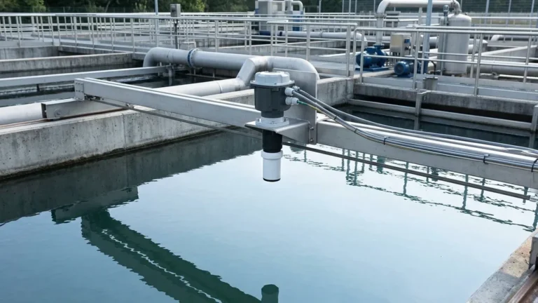
* Water and Wastewater: Monitoring levels in open channels, wet wells, and chemical dosing tanks. They are ideal here because the non-contact nature prevents fouling from raw sewage or corrosive additives.
* Chemical Processing: Measuring levels in storage tanks for acids, bases, and solvents where contact-based sensors would corrode or require frequent cleaning.
* Food and Beverage: Used in non-pressurized storage of juices, oils, and water. The non-contact design ensures hygienic standards are met as no part of the sensor enters the product.
* Industrial Automation: Integrated into PLC/SCADA systems via 4-20mA or Modbus RS485 for automated pump control and overflow prevention.
Frequently Asked Questions (FAQ)
Q: Can ultrasonic sensors measure the level of solids?
A: Yes, but with caveats. Solids like plastic pellets, grain, or coal often have an uneven surface (angle of repose), which scatters the echo. A lower-frequency sensor with a higher power output is typically required, and the effective range is usually reduced by 50% compared to liquids.
Q: How does wind affect open-air ultrasonic measurements?
A: In outdoor applications like reservoir or river monitoring, strong winds can "blow" the ultrasonic pulse away or create turbulence that disrupts the signal. Using a stilling well or a protective sunshade/windshield can help stabilize readings.
Q: What is the difference between a level transmitter and a level switch?
A: A level switch provides a discrete signal (on/off) at a specific point, whereas an ultrasonic level transmitter provides continuous measurement of the entire range, allowing for precise inventory tracking and trend analysis.
Q: Can I use an ultrasonic sensor in a pressurized tank?
A: Generally, no. Most ultrasonic transducers are designed for atmospheric conditions. Increased pressure changes the speed of sound significantly and can damage the transducer face. For pressurized vessels, radar level technology is the standard recommendation.
For technical specifications on specific models or to discuss a custom OEM/ODM requirement, engineers are encouraged to Review product options and application support to find the most cost-effective solution for their specific process needs.