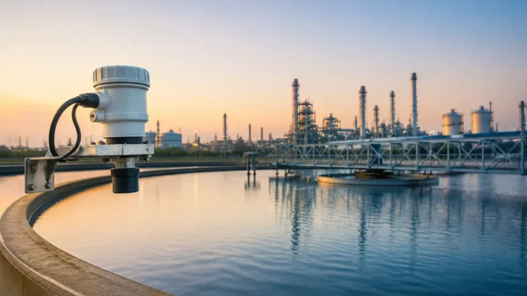
Ultrasonic Level Transmitter Frequency Range
Ultrasonic Level Transmitter Frequency Range: A Technical Selection Guide
In industrial process control, selecting the right instrumentation requires a deep understanding of the physics governing the measurement. For non-contact level sensing, Ultrasonic Level Meters remain a primary choice due to their cost-effectiveness and reliability in diverse environments. However, one of the most critical specifications for an engineer to evaluate is the ultrasonic level transmitter frequency range.
The frequency at which an ultrasonic transducer operates dictates the instrument’s effective measurement distance, its ability to penetrate atmospheric interference, and its overall accuracy. This guide examines the relationship between frequency and performance, providing practical insights for selecting the appropriate sensor for water treatment, chemical processing, and industrial automation.
Measurement Principles of Ultrasonic Technology
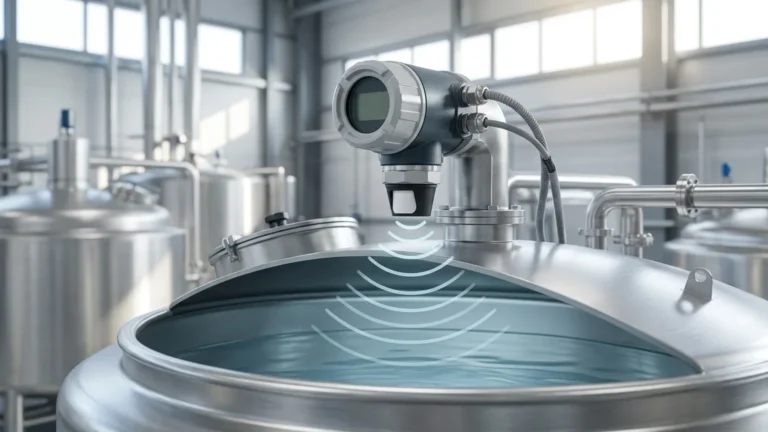
Ultrasonic level measurement is based on the "Time-of-Flight" (ToF) principle. The instrument’s transducer acts as both a transmitter and a receiver. It emits a mechanical sound wave at a specific frequency—well above the range of human hearing—which travels through the air or gas space in a tank, reflects off the surface of the material (liquid or solid), and returns to the sensor.
The distance is calculated using the formula:
Distance = (Speed of Sound × Time) / 2
Because the speed of sound in air is approximately 343 meters per second (at 20°C), the transmitter can determine the level by subtracting the measured distance from the total tank height. The ultrasonic level transmitter frequency range typically falls between 20 kHz and 80 kHz. The choice of frequency is a trade-off between range and resolution: lower frequencies travel further but have wider beam angles and lower resolution, while higher frequencies offer precision at the cost of distance.
Decoding the Ultrasonic Level Transmitter Frequency Range
When reviewing technical specifications from manufacturers like Welk, you will notice that different models operate at distinct frequencies. Understanding why these frequencies are chosen is essential for application engineering.
Low-Frequency Transducers (20 kHz – 30 kHz)
Low-frequency waves have longer wavelengths, which allow them to travel greater distances without significant attenuation (loss of energy). These are typically used for long-range measurements, often up to 30 meters (approx. 98 ft) or even 40 meters (approx. 131 ft) in specific configurations.
* Advantages: Excellent signal strength over long distances; better performance in dusty environments (such as grain silos) because the longer waves can "wrap around" small particles rather than being scattered by them.
* Disadvantages: Larger transducer size and a larger "dead zone" (blocking distance). They also typically have a wider beam angle, requiring more clearance from tank walls and internal obstructions.
Medium-Frequency Transducers (40 kHz – 50 kHz)
This is the most common range for standard industrial liquid level applications. It provides a balance between a respectable measurement range—usually up to 10 or 15 meters (33 to 49 ft)—and a compact sensor housing.
* Advantages: Versatile for most water and wastewater applications; moderate dead zone (typically 0.25m to 0.5m).
* Disadvantages: May struggle with heavy foam or very high-intensity dust compared to lower-frequency units.
High-Frequency Transducers (60 kHz – 80 kHz)
High-frequency sensors are designed for short-range, high-precision applications. These are often found in small chemical tanks or open channel flow measurement where accuracy within a few millimeters is required.
* Advantages: Very small dead zones (as low as 0.1m or 4 inches); narrow beam angles which allow for installation in narrow pipes or tanks with internal agitators; high resolution.
* Disadvantages: Limited range, usually capped at 5 to 7 meters (16 to 23 ft); highly susceptible to signal attenuation from steam, vapor, or heavy dust.
Technical Selection Table: Frequency vs. Application
The following table provides a general reference for matching the ultrasonic level transmitter frequency range to specific process requirements.
| Frequency Range | Typical Max Range | Typical Dead Zone | Primary Applications |
| :— | :— | :— | :— |
| 20 – 25 kHz | 25m – 40m | 0.8m – 1.2m | Tall silos, large reservoirs, solids/powders |
| 30 – 40 kHz | 15m – 25m | 0.5m – 0.8m | Large chemical storage, deep sumps |
| 40 – 55 kHz | 8m – 15m | 0.3m – 0.5m | Water treatment, standard liquid tanks |
| 60 – 80 kHz | 0.3m – 6m | 0.1m – 0.25m | Small process vessels, open channel flumes |
Practical Installation Considerations
Selecting the correct frequency is only half the battle; the physical installation must account for the characteristics of that frequency.
1. The Dead Zone (Blocking Distance)
Every ultrasonic sensor has a "dead zone" immediately in front of the transducer face where it cannot accurately process a return signal. This is because the transducer needs time to stop vibrating from the transmission pulse before it can listen for the echo. Higher frequency sensors have shorter vibration decay times, resulting in smaller dead zones. Always mount the sensor high enough so that the maximum liquid level never enters the dead zone.
2. Beam Angle and Obstructions
The ultrasonic pulse travels in a cone shape. The "beam angle" is usually defined as the point where the energy drops by 3dB. Lower frequency sensors tend to have wider beam angles (10° to 12°), while higher frequency sensors can be as narrow as 5° to 6°. If a tank has internal ladders, heating coils, or agitators, a high-frequency sensor with a narrow beam is preferred to avoid false echoes from these obstructions.
3. Mounting Position
* Avoid the center: Do not mount the sensor in the exact center of a domed tank, as this can focus parasitic echoes.
* Wall distance: Maintain a distance from the tank wall of at least 1/6th of the tank height to prevent the beam from hitting the wall.
* Inlet interference: Ensure the sensor is not positioned directly above the fill stream, which will cause signal turbulence and erratic readings.
Environmental Limitations and Challenges
While Ultrasonic Level Meters are robust, the physics of sound transmission imposes certain boundaries:
* Vacuum: Sound cannot travel in a vacuum. Ultrasonic sensors will not work in vessels under total vacuum.
* Temperature Gradients: The speed of sound changes with temperature. While Welk transmitters include integrated temperature compensation, extreme temperature gradients (e.g., a very hot liquid with cold air above it) can cause refraction of the sound wave, leading to errors.
* Heavy Foam: Foam acts as an acoustic absorber. If a process creates thick, dense foam, the ultrasonic signal may be absorbed rather than reflected. In such cases, a lower frequency sensor may provide better penetration, but often a contact-based technology or radar is required.
* High Pressure: In high-pressure environments, the density of the gas changes, which affects the speed of sound and the efficiency of the transducer’s coupling to the medium.
Why Frequency Choice Matters for OEM/ODM Services
For industrial automation providers and system integrators, the ability to customize the ultrasonic level transmitter frequency range is a significant advantage. Welk provides OEM/ODM services that allow for the optimization of transducer frequency based on specific tank geometries or material properties. For instance, a custom 30 kHz sensor might be integrated into a specialized mobile tanker system where long-range and vibration resistance are paramount, whereas a 75 kHz micro-sensor might be designed for laboratory-scale chemical dispensers.
Frequently Asked Questions (FAQ)
Q: Does a higher frequency always mean better accuracy?
A: Not necessarily. While higher frequencies offer better resolution (the ability to distinguish between two close objects), accuracy is also dependent on temperature compensation and signal processing algorithms. In a dusty silo, a high-frequency sensor might be less accurate because it loses the signal entirely, whereas a low-frequency sensor remains reliable.
Q: Can I use an ultrasonic transmitter for solids?
A: Yes, but you must typically use a lower frequency (20-30 kHz) and a higher power output. Solids like powders or granules do not reflect sound as efficiently as liquids and often create an uneven surface that scatters the signal. A lower frequency helps overcome these losses.
Q: How do I handle vapors or steam?
A: Steam and heavy vapors change the density of the air, which alters the speed of sound. If the vapor concentration is constant, the sensor can be calibrated for it. However, if it fluctuates, it may cause significant measurement drift. High-frequency sensors are generally more affected by vapor than low-frequency ones.
Q: What is the impact of the beam angle on sensor selection?
A: The beam angle determines how much space the sensor "sees." A wide beam angle is more likely to hit tank walls or internal structures. If your tank is narrow or crowded, you should select a higher frequency transmitter which naturally offers a narrower beam.
Conclusion
The ultrasonic level transmitter frequency range is a fundamental specification that determines the success of a level measurement application. By balancing the need for range against the requirements for precision and the constraints of the installation environment, engineers can ensure long-term, maintenance-free operation. Whether managing water levels in a municipal reservoir or monitoring corrosive chemicals in a process plant, understanding the relationship between frequency and acoustic behavior is key to choosing the right instrument from the Welk portfolio.
Download Ultrasonic Level Transmitter Frequency Range as a PDF