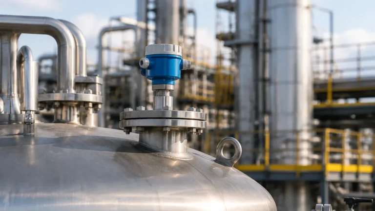
Guided Wave Radar Interface Level Transmitter
Guided Wave Radar Interface Level Transmitter: An Engineering Guide to Dual-Phase Measurement
In complex industrial processes, monitoring the total level of a vessel is often insufficient. Engineers frequently encounter scenarios where two immiscible liquids coexist in a single tank—such as oil over water, solvent over aqueous solutions, or condensed hydrocarbons over process water. Accurately identifying the transition point between these two layers is critical for process control, separation efficiency, and inventory management. The guided wave radar interface level transmitter has emerged as the most reliable technology for these applications, offering precision where traditional hydrostatic or buoyancy-based methods often fail.
This guide examines the technical principles, selection criteria, and installation requirements for utilizing guided wave radar (GWR) technology in interface measurement, providing a factual framework for instrumentation engineers and procurement specialists.
Measurement Principles: Time Domain Reflectometry (TDR)
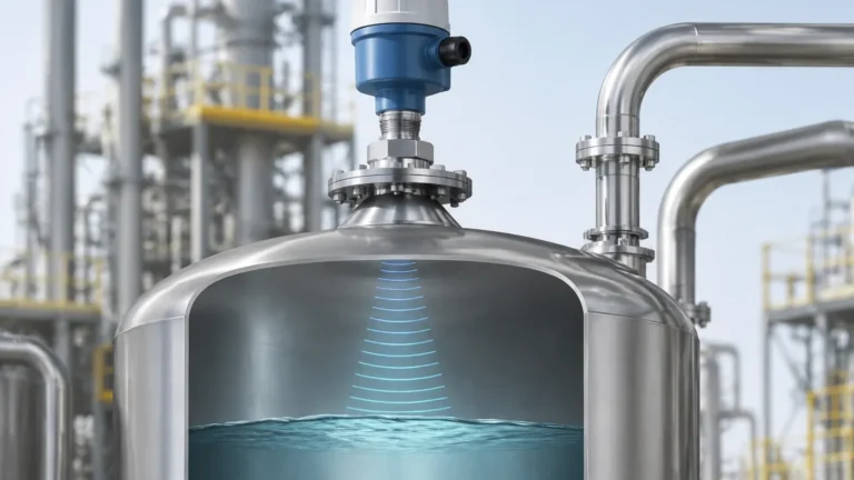
Guided wave radar operates on the principle of Time Domain Reflectometry (TDR). Unlike non-contact Radar Level Meters which broadcast electromagnetic pulses through the air, GWR transmitters conduct high-frequency, low-amplitude microwave pulses along a physical probe (waveguide).
The Physics of Reflection
When the pulse travels down the probe and hits a medium with a different dielectric constant ($ε_r$), a portion of the pulse energy is reflected back to the transmitter. The remaining energy continues through the medium until it hits the next transition point.
1. Total Level Reflection: The first reflection occurs at the surface of the upper liquid. Because the upper liquid (e.g., oil) typically has a low dielectric constant ($ε_r ≈ 1.9$ to $4.0$), only a fraction of the signal is reflected.
2. Interface Reflection: The remaining signal travels through the upper liquid at a reduced velocity (governed by the dielectric of that liquid) and reflects off the interface of the lower liquid. The lower liquid (e.g., water) usually has a high dielectric constant ($ε_r ≈ 80$), resulting in a much stronger second reflection.
By measuring the time-of-flight for both reflections and compensating for the signal slowdown in the upper medium, the transmitter calculates both the total level and the interface level simultaneously.
Critical Selection Criteria for Interface Measurement
For a guided wave radar interface level transmitter to function correctly, specific process conditions must be met. Failure to account for these variables is the leading cause of measurement error in the field.
1. Dielectric Constant Differential
The most fundamental requirement is that the upper liquid must have a lower dielectric constant than the lower liquid. Ideally, the difference between the two constants should be greater than 10. If the upper liquid has a high dielectric (such as an alcohol-based solvent over water), the signal may be entirely reflected at the first surface, leaving no energy to detect the interface.
2. Upper Layer Thickness
The upper liquid layer must be thick enough for the transmitter to distinguish between the two reflection pulses. Most modern GWR transmitters require a minimum upper layer thickness of 50 mm to 100 mm (approximately 2 to 4 inches) to resolve the interface accurately. If the layer is thinner than this "resolution zone," the two pulses may overlap, leading to a loss of interface signal.
3. Emulsion and "Rag" Layers
In many separation processes, the transition between liquids is not a clean line but a murky emulsion or "rag layer." This layer consists of a mixture of both liquids and often contains suspended solids or waxes. Because an emulsion has a gradient dielectric constant, it scatters the radar signal rather than reflecting it cleanly. If the emulsion layer exceeds 50 mm in thickness, the interface signal may become too weak to detect reliably.
Probe Type Selection Table
The choice of probe (waveguide) is determined by the vessel geometry, the viscosity of the fluids, and the presence of agitation.
| Probe Type | Best For | Advantages | Limitations |
| :— | :— | :— | :— |
| Coaxial Probe | Clean liquids, low dielectric upper layers | Highest signal-to-noise ratio; immune to tank internal interference. | Prone to clogging if liquids are viscous or contain solids. |
| Twin Rod/Cable | Long ranges, medium viscosity | Better signal strength than single rods; less prone to buildup than coaxial. | Requires more clearance from tank walls and internals. |
| Single Rod/Cable | Viscous liquids, bypass chambers | Easiest to clean; handles coating and buildup well. | Weakest signal; requires a stilling well or bypass for interface accuracy. |
Installation Considerations and Constraints
Proper installation is paramount to ensuring the accuracy of a guided wave radar interface level transmitter. Engineers should adhere to the following technical constraints:
Nozzle Dimensions
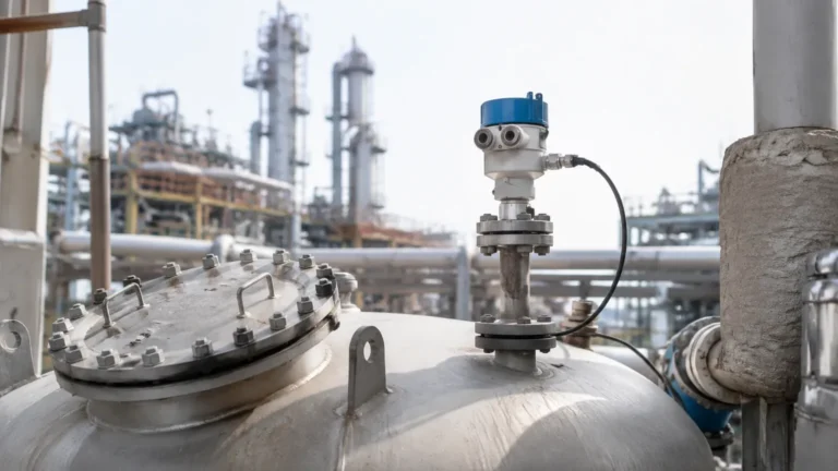
The mounting nozzle should be as short and wide as possible. A long, narrow nozzle creates parasitic reflections (ringing) that can interfere with the detection of the upper liquid surface, especially if the tank is nearly full. For coaxial probes, nozzle diameter is less critical, but for single-rod probes, the nozzle must be considered a part of the waveguide system.
Stilling Wells and Bypass Chambers
In tanks with heavy agitation, foam, or internal obstructions (like heating coils), installing the GWR probe inside a stilling well or an external bypass chamber is highly recommended. This provides a calm surface for measurement and increases the signal strength for single-rod probes by concentrating the electromagnetic field. When using a bypass chamber, ensure the chamber material is compatible with the process fluid and that the diameter allows for sufficient clearance (typically 50 mm to 100 mm).
Dead Zones (Blocking Distances)
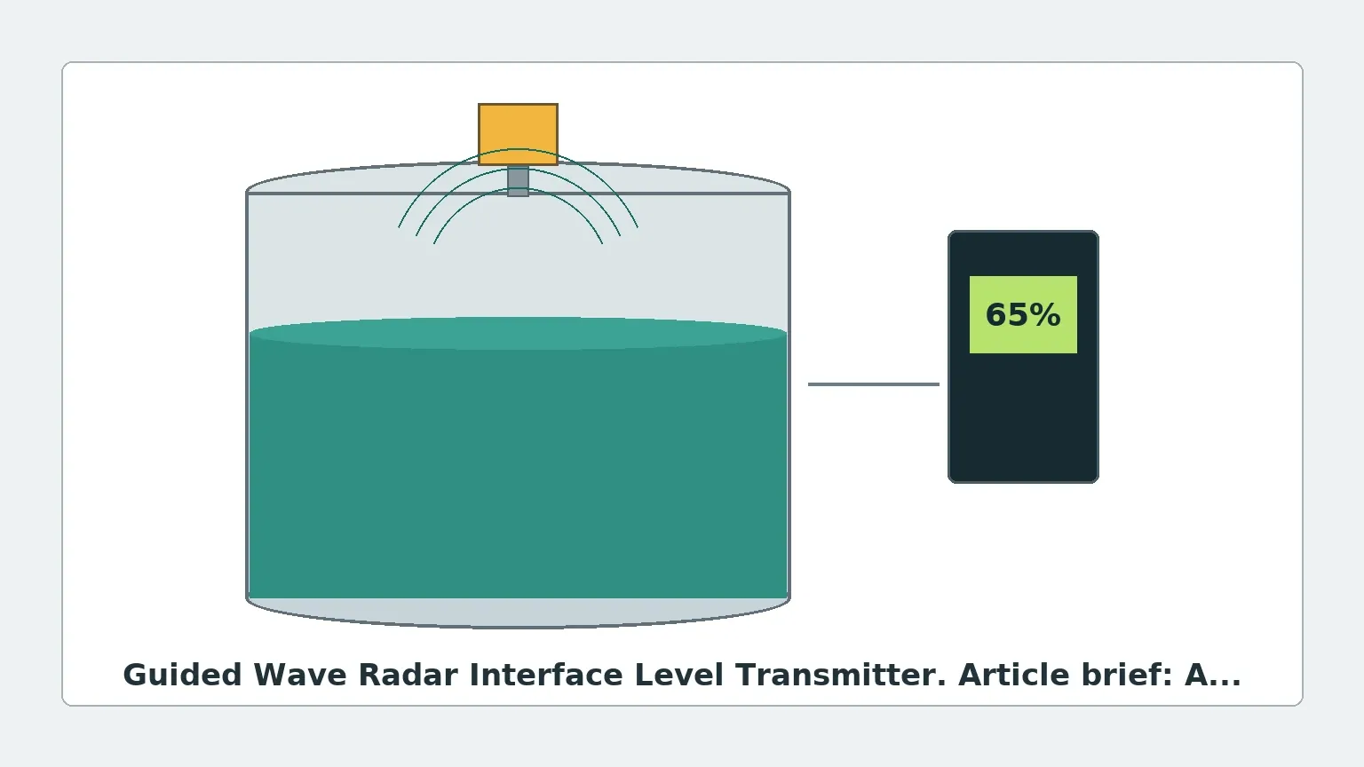
All GWR sensors have an "Upper Dead Zone" near the process connection and a "Lower Dead Zone" at the end of the probe. Measurement in these zones is either impossible or significantly less accurate. When specifying probe length, ensure the operational interface range falls within the "active" portion of the probe.
Application Risks and Limitations
While GWR is robust, it is not a universal solution. Engineers must be aware of the following risks:
* Coating and Buildup: While GWR handles thin coatings better than ultrasonic sensors, heavy, conductive buildup on the probe can attenuate the signal or cause "ghost" reflections. In such cases, single-rod probes with PTFE insulation are preferred.
* Varying Dielectrics: If the dielectric constant of the upper liquid changes significantly due to temperature or composition shifts, the interface calculation will drift. High-end transmitters offer dynamic dielectric compensation to mitigate this.
* Gas Phase Compensation: At very high pressures (e.g., saturated steam or high-pressure CO2), the dielectric of the gas phase above the liquid increases, slowing the signal. This can lead to an error in the total level measurement. Specific GWR models include a reference reflection to compensate for gas-phase variations.
International Buyer Checklist: Technical Specifications
When sourcing a guided wave radar interface level transmitter from a global manufacturer like Welk, providing comprehensive process data ensures the equipment is fit for purpose. Buyers should confirm the following:
1. Fluid Characteristics: Dielectric constants of both liquids, viscosity, and the likelihood of an emulsion layer.
2. Process Conditions: Maximum and minimum operating pressure and temperature. High-temperature applications may require integrated cooling fins for the electronics.
3. Wetted Materials: Standard 316L stainless steel is common, but aggressive chemicals may require Hastelloy C-276, Monel, or PTFE-coated probes.
4. Connection Type: Flanged (ANSI/DIN) or threaded (NPT/G) connections, and whether a hygienic connection is required for food or pharmaceutical use.
5. Output Protocol: Standard 4-20mA with HART is common, but Foundation Fieldbus or Modbus may be required for integration into modern DCS/PLC systems.
Frequently Asked Questions (FAQ)
Q: Can GWR measure the interface if the top liquid is conductive?
A: No. If the upper liquid is conductive (e.g., water over a heavier chlorinated solvent), the radar signal will be entirely reflected at the first surface. GWR interface measurement only works when the upper liquid is non-conductive.
Q: How does GWR compare to Magnetic Level Gauges for interface?
A: Magnetic level gauges rely on buoyancy and a float weighted to the specific gravity (SG) of the interface. If the SGs of the two liquids change, the float may sink or float too high. GWR is generally more accurate as it relies on electrical properties (dielectric) rather than mechanical buoyancy.
Q: Is it possible to cut the probe to length in the field?
A: Most rod and cable probes can be shortened in the field. However, the transmitter's configuration must be updated to reflect the new probe length to maintain accuracy. Coaxial probes are more difficult to modify and should be ordered to the exact required length.
Conclusion
The guided wave radar interface level transmitter represents a significant advancement in industrial instrumentation, providing a reliable method for managing dual-phase liquid systems. By understanding the dielectric relationship between fluids and selecting the appropriate probe geometry, facilities can achieve precise control over separation and storage processes. For further technical details on various radar technologies, including non-contact options, engineers may review the diverse range of Radar Level Meters available for industrial automation.
Download Guided Wave Radar Interface Level Transmitter as a PDF